
Schematic
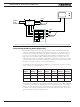
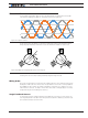

Brushless Motor Connections and Operation
98 Advanced Digital Motor Controller User Manual V1.8, August 28, 2017
Sensorless Configuration and Calibration
The controller’s default configuration will typically work with any motor. However, faster and
more consistent motor startup will be achieved by performing these setup and calibration steps:
1. Make sure the battery volts and if possible the maximum load on the motor is set. If
either changes the procedure will need to be repeated.
2. Configure motor channels as sensorless.
3. Set motor command 10 or -10 and check if the motor starts and rotates smoothly
when using the default setting. If not modify Sensorless Start-Up Power (SSP) accord-
ingly. Higher the motor friction, the higher the value of SSP should be.
4. Type on console %clmod 4 (for channels 1). This will cause the controller to enter the
sensorless calibration mode.
5. Set Motor Command 10 or -10 and wait until the rotation of the motor becomes
smooth and stable.
6. Wait for a couple of seconds and stop the motor.
7. Monitor the Hall Speed with motor command 10 and -10. Make sure the speed is the
same in both directions symmetrical. If not then choose as last the motor command
which gives the smallest speed.
8. Type on console %clmod 0 to exit the calibration mode
9. Type on console %eesav, in order to save the value on flash.
Startup should be quicker and more efficient after these steps. Calibration values can be
viewed, and manually adjusted if needed, using the SST configuration.
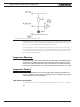
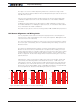
Sensorless brushless motors only require their 3 wires to be connected to the controller’s
U, V and W terminals. The wires can be connected in any order. If the motor spins in the
opposite direction than the desired one, simply invert any two motor wires. It is also pos-
sible to use the MDIR Motor Direction configuration parameter.
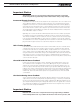
Verifying Commutation Timing
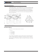
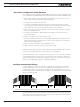
In trapezoidal modes, with an oscilloscope it is possible to verify that the commutation,
either in Hall sensors or sensorless mode, is happening at the optimal time. On a mo-
tor driven by the motor controller, place a probe between ground and any of the motor
phases. Verify that the voltage looks like the shape on the figure 8-6. Look for symmetrical
ramps on the left and right.
T TT/2 T/2T/2 T/2T
Figure 8-6. Ground to Phase voltage waveform on motor with correct commutation
An alternate method is to run the motor in the forward and then in the reverse direction.
Verify that for a give command level in open loop, the motor reaches the identical speed
and consumes the same amount of current.