
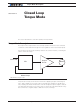
Schematic
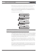


Torque Mode Using an External Amps Sensor
Advanced Digital Motor Controller User Manual 147
results use an amps limit that is at least 50% than the controller’s max rating. On newer
Brushless motor controllers, amps sensors are placed at the motor output and motor amps
are measured directly. Torque mode will work effectively on these models.
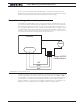
Torque Mode Using an External Amps Sensor
The limitations described above can be circumvented using an external amps sensor de-
vice such as the Allegro Microsystems ACS756 family of hall sensors. These inexpensive
devices can be inserted in series with one of the motor leads while connected to one of
the controller’s analog inputs. Since it is directly measuring the real motor amps, this sen-
sor will provide accurate current information in all load and regeneration conditions. This
technique only works for DC brushed motors. On brushless motors, the current in the mo-
tor wires is AC and therefore an external sensor cannot be used.
Motor
+5V
GND
Ana
Allegro ACS756
Current Sensor
Controller
FIGURE 13-2. Torque external sensor
To operate in torque mode, simply configure the selected analog input range to this of the
sensor’s output at the min and max current that will correspond to the -1000 to +1000
command range. Configure the analog input as feedback for the selected motor channel.
Then operate the controller in Position Tracking Mode (See “Position Tracking Mode” on
page 121). While the controller will not actually be tracking position, it will adjust the out-
put based on the command and sensor feedback exactly in the same fashion.