
Schematic


CAN Networking on Roboteq Controllers
160 Advanced Digital Motor Controller User Manual V1.8 August 28, 2017
18
915
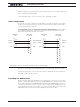
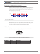
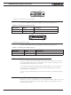
FIGURE 15-4. DB15 Connector pin locations
The pins on the DB15 connector are mapped as described in the table below.
TABLE 15-2. CAN Signals on DB15 connector
Pin Number Signal Description
6 CAN_L CAN bus low
7 CAN_H CAN bus high
1
15
69
13
14 25
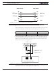
FIGURE 15-5. DB25 pin locations
The pins on the DB25 connector are mapped as described in the table below.
TABLE 15-3. CAN Signals od DB25 connector
Pin Number Signal Description
8 CAN_L CAN bus low
20 CAN_H CAN bus high
CAN and USB Limitations
On some controller models CAN and USB cannot operate at the same time. On control-
lers equipped with a USB connector, if simultaneous connection is not allowed, the con-
troller will enable CAN if USB is not connected.
The controller will automatically enable USB and disable CAN as soon as the USB is con-
nected to the PC. The CAN connection will then remain disabled until the controller is
restarted with the USB unplugged.
See the controller model datasheet to verify whether simultaneous CAN and USB is sup-
ported.
Basic Setup and Troubleshooting
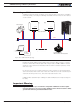
CANbus is very easy to setup: Simply connect the CANH and CANL to a pair of wires with
at least one resistor somewhere along the cable. Enable the desired CAN protocol and
speed using the PC utility.