
Data Sheet
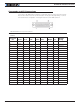


Status LED Flashing Patterns
GBL2xxx Motor Controller Datasheet 11
USB communication
Use USB only for configuration, monitoring and troubleshooting. USB is not a reliable
communication method when used in a electrically noisy environments and communica-
tion will not always recover after it is lost without unplugging and replugging the connec-
tor, or restarting the controller. Always prefer RS232 communication when interfacing to a
computer. USB and CAN can operate at the same time on the GBL2660. Plugging USB to
a com puter will not disable the CAN interface.
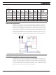
RS485 Communication
The FBL2360 has a half-duplex RS485 interface. Two signals are present on the 25-pin
DSub connector for connecting to RS485 networks. Connecting these two wires with the
correct polarity is all that is needed to establish a connection. The RS485+ is the positive
signal and RS485- is the inverted signal. Once enabled, the RS485 can be used to commu-
nicate data under the Modbus protocol, or Roboteq’s native serial commands.
Ethernet Communication
Ethernet communication is only available on the E versions of the controller. The con-
nection port is located on the top of the unit for easy and rapid access. Communication
occurs via TCP/IP. Commands can be in Serial over TCP and Modbus TCP. Serial over TCP is
the preferred method to access all native commands.
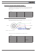
Two LEDs are present on the Ethernet jack, as shown in Figure 13. The left Yellow LED
will be On when operating as 100 Mbps connection and Off when as 10 Mbps. The right
Green LED will blink when data activity is present.
FIGURE 12. Ethernet LED Configuration
Status LED Flashing Patterns
After the controller is powered on, the Power LED will tun on, indicating that the controller
is On. The Status LED will be flashing at a 2 second interval. The flashing pattern and color
provides operating or exception status infor mation.