
Data Sheet


Use of Safety Contactor for Critical Applications
GBL2xxx Motor Controller Datasheet 5
Note 3: Insert a high-current diode to ensure a return path to the battery during regenera-
tion in case the fuse is blown.
Note 4: Optionally ground the VMot tabs when the controller is Off if there is any concern
that the motors could be made to spin and generate voltage in excess of 60V.
Note 5: Connect the controller’s bottom plate to a wire connected to the Earth while the
charger is plugged in the AC main, or if the controller is powered by an AC power supply.
Note 6: Beware not to create a path from the ground pins on the I/O connector and the
battery minus terminal.
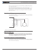
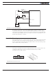
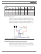
Single Channel Wiring
On the Single Channel GBL26xxS, the each of the motor wire must be connected to both
output tabs of the same letter, as shown in Figure 3, below. Use the Encoders and/or Hall
sensors of Channel 1 for operation.
FIGURE 3. Single Channel Wiring Diagram
Important Warning
This wiring must be done only on the single channel version of the controller. Paral-
leling the wires on a dual channel product will cause permanent damage. Verify that
your controller is an GBL2660S before you wire in this manner.
Use of Safety Contactor for Critical Applications
An external safety contactor must be used in any application where damage to property or
injury to person can occur because of uncontrolled motor operation resulting from failure
in the controller’s power output stage.
U1
V1
W1
U2
V2
W2
U
V
W