
Data Sheet


Commands and I/O Connections
GBL2xxx Motor Controller Datasheet 9
Commands and I/O Connections
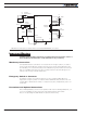
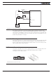
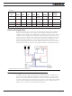
Connection to RC Radio, Microcomputer, Joystick and other low current sensors and actu-
ators is done via the 25 connector. The functions of many pins vary depending on control-
ler model and user configuration. Pin assignments are found in Table 5, below.
FIGURE 9. Main Connector Pin Locations
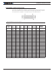
TABLE 5.
Connector
Pin Power Dout Com Pulse Ana Dinput Enc
Default
Config
1 GND
14 5VOut
2 RS TxD RS232Tx
15 RC1 ANA1 DIN1 RCRadio1
3 RS RxD RS232Rx
16 RC2 ANA2 DIN2 RCRadio2
4 RC3 ANA3 DIN3 AnaCmd1 (1)
17 RC4 ANA4/EXC DIN4 AnaCmd2 (1)
5 GND
18 DOUT1 Motor Brake 1
6 DOUT2 Motor Brake 2
19 DOUT3 Contactor
7 DOUT4 Unused
20 CANH Unused
8 CANL Unused
21 RC5 ANA5 DIN5 ENC2A Unused
9 ASIN1 DIN9 Unused
22 RC6 ANA6 DIN6 ENC2B Unused
10 ACOS1 DIN10 Unused
23 485+ RS485+
11 485- RS485-