
Data Sheet


Diagnostic LEDs
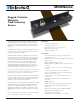
MGSWxxxx Magnetic Sensor Datasheet 10
The Gyroscope values can be read via USB, Serial or CANbus. The Z sensor value is also automatically transmit-
ted to a Roboteq motor controller, along with the magnetic sensor data, using a single wire and the MultiPWM
mode. Finally angle integration is implemented out of the gyroscope data, using ANG query and command.
The angle is given in degrees*10.
The Gyroscope values are integers with the following range:
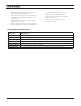
TABLE 5.
Resolution Value Range Divider
+/-250 +/-25000 100
+/-500 +/-5000 10
+/-2000 +/-20000 10
Note: Begining with v3.0 of the MGS firmware, the Gyroscope values are in dps*10 for all resolution op-
tions. This does not apply to older firmware versions.
FIGURE 11. Orientation of the Gyroscope Axis
Diagnostic LEDs
Since magnetic fields are invisible, the sensor is equipped with four LEDs to help with setup and troubleshoot-
ing. The LED positions are shown in Figure 2, on Page 4. The Power LED will light up when the sensor is on. The
Track Detect/Track Position LED is a dual usage LED that will light up when a track is present. The LED is bi-col-
or and will gradually shift to red when the track is at the left of the sensor, and to green as the track moves to
the right. Two additional LEDs will turn on when left or right markers are detected.
Interfacing the Sensor to PLCs
The sensor can be fully interfaced to a PLC via its CANbus or RS232 interface. It is also possible to use the
PWM and analog inputs. The CAN and RS232 mode are the preferred interfaces as these enable the full func-
tionality of the sensor, including markers detections.