
Data Sheet
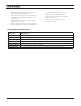


I/O and Power Connector
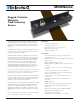
MGSWxxxx Magnetic Sensor Datasheet 4
USB
Power &
IO Connector
Left Side
Relative to Forward
Direction
Right Side
Relative to Forward
Direction
Power
Forward
Reference
Direction
Tape Detect
Right Marker
Left Marker
FIGURE 2. Sensor Outline
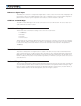
I/O and Power Connector
The MGSWxxxx is fitted with a waterproof 8-pin M12-type male. Connector for powering the sensor and ac-
cessing all the I/O signals. The connector pins are identified in the table below.
FIGURE 3. Connector Pin Locations
TABLE 2.
Connector
Pin Signal Description
1 Power 4.5V to 30V DC Power supply input
2 RxData RS232 Receive Data
3 TxData RS232 Transmit Data
4 CANL CANbus Low
5 CANH CANbus High
6 Analog(1) Out 0-3V (1.5V center) Analog track position
7 PWM(2) Out Track position PWM output
8 GND Ground
Note 1: Analog Output can be configured as Tape and Marker Detect when operatin in PWM mode
Note 2: PWM Output can be configured as Tape and Marker Detect when operating in Analog mode