
Data Sheet

6 SBL13xx Motor Controller Datasheet Version 1.1 March 29, 2018
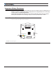
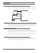
Hall Sensors Connection
Connection to the Hall Sensors is done using a special connector on the right side of the controller. The Hall sensor
connector is a 5-pin JST PH, model PHR-5. Pin assignments are in Table 1, below.
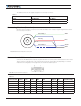
GND
Hall A
Hall B
Hall C
5V
FIGURE 4. Connector Wiring Diagram
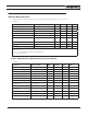
TABLE 1.
Pin Number 1 2 3 4 5
Signal 5V Hall C Hall B Hall A Ground
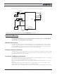
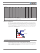
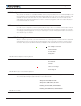
Hall Sensor vs Motor Output sequencing
The controller requires the Hall sensors inside the motor to be 120 degrees apart. The controller’s 3-phase
bridge will activate each of the motor winding according to the sequence shown in the figure below.
U
VW
1234561
1
2
2
3
3
4
4
5
5
6
6
Hall A
Hall B
Hall C
U
V
W
-
++
++ ++
++ ++
++
-- --
-- --
-- -
FIGURE 5. Hall Sensors Sequence
Connection to Analog Sin/Cos Absolute Encoder (A-version)
The SBL13xxA have two high-speed analog inputs that can be used to capture absolute angle position from
angular sensors with sin/cos voltage outputs. The signal must be 0-5V max with the 0 at 2.500V.