
Data Sheet
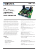

SBL13xx Motor Controller Datasheet 9
Status LED Flashing Patterns
CAN Bus Operation
The controller can interface to a standard CAN Bus network, using 4 possible protocols: Standard CANOpen, and
three proprietary schemes (MiniCAN, RawCAN and RoboCAN). Please refer to the User Manual for details. USB
and CAN can operate at the same time only on the SBL1xxxA. On the SBL1xxx, the controller starts up with
CAN available, but CAN will be disabled as soon as the controller is plugged into USB. To re-enable CAN, discon-
nect USB and restart the controller.
USB communication
Use USB only for configuration, monitoring and troubleshooting. USB is not a reliable communication method
when used in a electrically noisy environments and communication will not always recover after it is lost with-
out unplugging and replugging the connector, or restarting the controller. Always prefer RS232 communication
when interfacing to a computer.
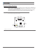
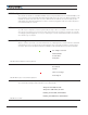
Status LED Flashing Patterns
After the controller is powered on, the Power LED will tun on, indicating that the controller is On. The Status LED
will be flashing at a two seconds interval. The flashing pattern and color provides operating or exception status
information. Note that model SBL13xxA had bicolor Red/Green LED and SBL13xx has monochrome Red LED.
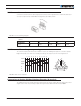
RS232/USB Mode
Idle - Waiting for Commandi
RC Pulse Mode
Analog Mode
Under or Over Voltage
Power Stage Off
Short Detected
Overheat
FIGURE 9. Normal Operation Flashing Patterns
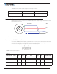
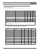
RS232/USB Mode
Idle - Waiting for Commandi
RC Pulse Mode
Analog Mode
Under or Over Voltage
Power Stage Off
Short Detected
Overheat
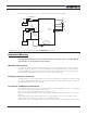
FIGURE 10. Exception or Fault Flashing Patterns
Additional status information may be obtained by monitoring the controller with the PC utility.
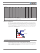
The communication LED gives status information on the CAN and USB.
Always off: No USB, No CAN
Always On: USB Active, No CAN
Flashing On: No USB, CAN Enabled
Flashing Off: USB Active, CAN Enabled
FIGURE 11. Com LED