
Data Sheet


Electrical Specifications
SDC3260 Motor Controller Datasheet 11
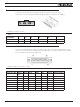
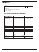
TABLE 3.
Parameter Measure point Min Typ Max Units
Note 1: Maximum regeneration voltage in normal operation. Never inject a DC voltage from a battery or
other fixed source
Note 2: No external voltage must ever be applied to Tx pin
Note 3: Non condensing
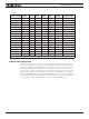
Power Stage Electrical Specifications (at 25oC ambient)
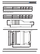
TABLE 4.
Continuous Max Current
per channel Measure point Min Typ Max Units
Battery Leads Voltage Ground to VMot 0 (1) 63 Volts
Motor Leads Voltage Ground to M+ and M- wires 0 (1) 63 (2) Volts
Power Control Voltage Ground to Power Control wire 0 (1) 65 Volts
Minimum Operating Voltage VMot or Pwr Ctrl wires 9 (3) Volts
Over Voltage protection range Ground to VMot 5 60 (4) 63 Volts
Under Voltage protection range Ground to VMot 0 5 (4) 63 Volts
Idle Current Consumption VMot or Pwr Ctrl wires 50 100 (5) 150 mA
ON Resistance (Excluding wire
resistance)
VMot to M+/-. Ground to M+/- 9.0 mOhm
Max Current for 30s Motor current 20 Amps
Continuous Max Current per
channel
Motor current 15(6) Amps
Current Limit range Motor current 2 20 (7) 20 Amps
Stall Detection Amps range Motor current 2 20 (7) 20 Amps
Stall Detection timeout range Motor current 1 500 (8) 65000 milli-
seconds
Short Circuit Detection
threshold (9)
Between Motor wires or
Between Motor wires and
Ground
100
(10)
Amps
Short Circuit Detection
threshold
Between Motor wires and
VBat
No Protection. Permanent damage
will result
Motor Acceleration/
Deceleration range
Motor Output 100 500
(11)
65000 milli-
seconds