
Data Sheet


8 SDC3260 Motor Controller Datasheet Version 1.3 January 23, 2018
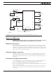
113
14 25
21
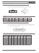
Pot 1
RS232
Ground
TxOut
RxIn
Motor Brake 1
Motor Brake 2
Contactor
Pot 2
RC Ch2RC Ch1
FIGURE 6. Factory Default Pin Assignments
Enabling Analog Commands
For safety reasons, the Analog command mode is disabled by default. To enable the An-
alog mode, use the PC utility and set Analog in Command Priority 2 or 3 (leave Serial as
priority 1). Note that by default the additional securities are enabled and will prevent the
motor from starting unless the potentiometer is centered, or if the voltage is below 0.25V
or above 4.75V. The drawing shows suggested assignment of Pot 1 to ANA1 and Pot 2 to
ANA4. Use the PC utility to enable and assign analog inputs.
USB communication
Use USB only for configuration, monitoring and troubleshooting the controller. USB is not
a reliable communication method when used in electrically noisy environments. Further,
communication will not always recover after it is lost without unplugging and replugging
the connector, or restarting the controller. RS232 communication is always preferred
when interfacing to a computer. USB and CAN will operate at the same time on the
SDC3260. Connecting to a com puter via the USB will not disable the CAN interface.
RS485 Communication
RS485 is an industry standard for defining serial communication. Due to its balanced sig-
naling, RS485 is effective over distances, even if other electrical signals are present. Its
stability makes it well suited for connecting multiple receivers to a single network.
You can operate RS485 in half-duplex mode and it is well suited for use with the Modbus
protocol. On the 25-pin connector, 2-pins are pins are present.