
Data Sheet


Status LEDs and Flashing Patterns
SDC3260 Motor Controller Datasheet 9
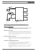
Status LEDs and Flashing Patterns
The controller is equipped with 3 LEDs. A Green Power LED, a Red/Green Status LED,
and a Yellow Communication LED.
After the controller is powered on, the Power LED will tun on, indicating that the controller
is On. The Status LED will be flashing at a 2 seconds interval. The flashing pattern and col-
or provides operating or exception status infor mation.
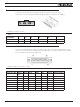
FIGURE 7. Normal Operation Flashing Patterns
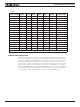
FIGURE 8. Exception or Fault Flashing Patterns
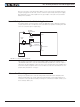
Additional status information may be obtained by monitoring the controller with the
PC utility.
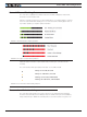
The communication LED gives status information on the CAN and USB.
Always off: No USB, No CAN
Always On: USB Active, No CAN
Flashing On: No USB, CAN Enabled
Flashing Off: USB Active, CAN Enabled
FIGURE 9. Communication LED Flashing Patterns
Measured and Calculated Amps
The controller includes Amps sensor in line with the motor terminals. Motor Amps are
therefore measured with precision. Battery Amps is estimated using the formula Battery
Amps = Motor Amps * PWM. This formula produces accurate results as long as the mo-