MessagePlus User’s Guide & Reference
This manual covers installation and operating instructions for the following U.S. Robotics modem: • Sportster MessagePlus external modem IMPORTANT MESSAGE: This product is capable of download speeds up to 56Kbps; however, the download speeds you experience may be lower due to varying line conditions. We are continuing to test and improve our modem technology to achieve faster speeds. Visit our Web site at http://www.usr.com for future updates and enhancements. 3Com, the 3Com logo, U.S.
Table of Contents U.S. ROBOTICS : THE INTELLIGENT CHOICE IN INFORMATION ACCESS™............................................ 1 WELCOME TO X2 INFORMATION ACCESS ................ 3 PRODUCT FEATURES .................................................. 5 FAX STANDARDS ................................................................... 5 SUMMARY OF FEATURES............................................ 7 PART I : EXTERNAL MODEM INSTALLATION ............ 9 SECTION A: EXTERNAL MODEM INSTALLATION WITH WINDOWS 3.X .....
SECTION E : TECHNICAL QUICK REFERENCE ....................... 41 Front Panel Lights (external modems).....................................41 Command Summary ...............................................................43 Command Set.........................................................................44 S-Registers.............................................................................53 The Serial Interface.................................................................
U.S. Robotics : The Intelligent Choice in Information Access™ ® C ongratulations! You have just purchased the Sportster MessagePlus faxmodem. Since 1976, U.S. Robotics has grown to become a key manufacturer and developer of information access technology. U.S. Robotics’ advanced technology allows you to use your faxmodem to open up a new world of information access.
2 Sportster MessagePlus
Welcome to x2 Information Access The latest breakthrough in online communications Until now, 33.6 Kbps was thought to be the practical limit for speed over standard phone lines. Now, x2 shatters that barrier, to bring you download speeds of up to 56 Kbps. However, due to FCC rules which restrict power output of your service provider’s modems, current download speeds are limited to 53Kbps. This modem is easily upgradeable to new features and enhancements as they become available.
x2 takes advantage of the typical network configuration found when an analog subscriber connects to a digitally connected server. Since x2 bypasses the analog-to-digital conversion in the downstream path, it can use nearly all of the available 64K network bandwidth. (Upstream data, typically less speed sensitive, travels at the standard V.34 rate.) The result is a completely new kind of transmission technique.
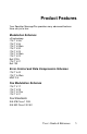
Product Features Your Sportster MessagePlus provides many advanced features. Here are just a few : Modulation Schemes x2 technology ITU-T V.34+ ITU-T V.34 ITU-T V.32bis ITU-T V.32 ITU-T V.23 ITU-T V.22bis ITU-T V.22 Bell 212A ITU-T V.21 Bell 103 Error Control and Data Compression Schemes ITU-T V.42 ITU-T V.42bis MNP 2-5 Fax Modulation Schemes ITU-T V.17 ITU-T V.29 ITU-T V.27ter ITU-T V.21 Fax Standards EIA 578 Class 1 FAX EIA 592 Class 2.
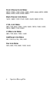
Front Channel Link Rates 33333, 37333, 41333, 42666, 44000, 45333, 46666, 48000, 49333, 50666, 52000, 53333, 54666, 56000. Back Channel Link Rates 14400, 16800, 19200, 21600, 24000, 26400, 28800, 31200 V.34+ Link Rates 4800, 7200, 9600, 12000, 14400, 16800, 19200, 21600, 24000, 26400, 28800, 31200, 33600 V.32bis Link Rates 4800, 7200, 9600, 12000, 14400 Additional Link Rates 300, 1200/75 (V.
Summary of Features Key Features of Sportster MessagePlus Sportster MessagePlus is the first product to include features that allow the user to receive fax and voice messages without the intervention of the PC. Sportster MessagePlus features a bank of Flash Memory for this purpose. Messages can be received even when the PC is not switched on. Voice messages can be retrieved from a remote location. Sportster MessagePlus comes with specially designed application software.
• 8 includes software designed specifically for use with Sportster MessagePlus. The software allows the user to take full advantage of all features in the product. Other software can be used for all standard modem functions. In order to use the autonomous features, however, we recommend using the software delivered with the product.
Part I : External Modem Installation Part I of this manual covers the installation of your external Sportster MessagePlus. The instructions are provided for both Windows 3.1/ 3.11 (hereafter jointly referred to as Windows 3.x) and Windows 95 users. Please refer to the section dealing with the operating system you use. The two sections are: Section A: External Installation with Windows 3.
How to Hook Up the Modem 1. Turn off your computer and any attached devices, such as a printer. 2. Connect the serial cable to the modem and to the computer. When looking for the serial port label on the back of your computer, look for ports labeled COM, MODEM, RS-232, or SERIAL. DO NOT select AUX, GAME, LPT, or PARALLEL. NOTE: Remember which serial port you selected. This information will be necessary when installing your communications software. 3.
6. Turn your modem on. 7. Turn your computer on. 8. Start Windows 3.x. Congratulations! You are ready to start using your Sportster MessagePlus.
How to connect the Modem to the Computer 1. Turn off your computer and any attached devices, such as a printer. 2. Connect the serial cable to the modem and to the computer. When looking for your serial port label on the back of your computer, select COM, MODEM, RS-232, or SERIAL. DO NOT select AUX, GAME, LPT, or PARALLEL. Note: Remember which serial port you selected. This information will be necessary when installing your communications software. 3.
6. Turn your modem on. 7. Turn your computer on. 8. Start Windows 95. How to Move Through the “New Hardware Found” Screens 1. This screen will come up when Windows restarts. If the Driver from disk... option is not already selected, choose it. Click on the OK button. 2. Insert the driver diskinto your disk drive. 3. When you see this screen, type in A:\. (If your disk drive has a different letter name, type that letter instead of A.
Click on the OK button. Windows will install the drivers for your new modem. 4. You can verify that the install was a success. When your desktop returns, click on the Start button and scroll up to Settings. 5. Scroll over to select Control Panel.
6. Double-click on the Modems icon. 7. In the Modems Properties screen, you should see Sportster MessagePlus Fax External listed. This indicates that your new Sportster MessagePlus is installed correctly.
8. Click on the OK button. Congratulations! You are now ready to start using your Sportster MessagePlus.
Part II : Beyond Setup Part II includes information which may not be necessary for installing your modem or fax/data/voice software, but will help to expand your knowledge of the modem and its capabilities.
Section A: Installing Fax/Data/Voice Software Your modem has been designed and tested using a wide range of communications software packages on the market. This section will walk you through some of the details you may need to know when installing communications software packages. Type of Modem Most communications software programs will ask you to select the type of modem you are using. Select a U.S. Robotics Sportster high speed modem. If that selection is not listed, pick Courier Dual Standard, V.
Flow Control • For hardware RTS/CTS. flow control (highly recommended), select • For software flow control, select XON/XOFF. NOTE: Disable the type of flow control (hardware or software) that you are not using. UART - Universal Asynchronous Receiver Transmitter (External Modems Only) 1. In DOS, at the Windows directory type: MSD 2. At the next prompt, type: C Find the UART Chip Used line and match it with the COM port column that your modem is attached to. That is your UART type.
Section B : Remote Voice Retrieval - whilst the modem is in Independent mode - To access your Voice messages remotely, you need to dial into the Sportster MessagePlus modem. Whilst the 'outgoing message' is being played, you must enter your pre-configured password on a touch-tone telephone handset (this can be set using the software application). You have three attempts to enter the correct password. If you fail to enter the correct password, the modem will 'abort' the call and go back 'on hook'.
Section C : Troubleshooting and Online Help Ressources PROBLEM DIAGNOSIS POSSIBLE SOLUTION P D 1 The computer or software will not recognize the modem. D D D D Your modem might not be turned on. You may have a COM/IRQ conflict. 1 1 You might not be entering modem commands in the proper manner. 1 You may need to reset your COM and IRQ settings. 1 If using an external modem, the COM port may not be enabled. Make sure the modem is turned on. The power switch is on top of external modems.
PROBLEM DIAGNOSIS POSSIBLE SOLUTION P D 1 P P 22 The modem displays double characters on your monitor. D The modem won’t go off hook to dial or doesn’t answer the phone. Both modems exchange carrier signals but fail to establish a link. D D Both the modem and software’s local character echoes are probably turned on. You might have a bad phone cord connection to your modem. 1 The software you are using might not have auto answer enabled. You may have a poor line connection.
PROBLEM DIAGNOSIS POSSIBLE SOLUTION P D 1 P Your modem won’t connect at 2400 bps with a 2400 bps modem. D Your screen keeps displaying random garbage characters. D D The modem you’re trying to connect with could be an older model that doesn’t support error control. You could have a conflict with the remote modem’s settings for word length, parity, and stop bits. Your software and modem might not be set to the same flow control settings.
PROBLEM DIAGNOSIS POSSIBLE SOLUTION P D 1 Your communicat ions software is reporting many cyclic redundancy check (CRC) errors and low characters per second (CPS). D D D D 24 You may have a bad phone line. Optimum flow control settings may not be enabled on your modem. The serial port rate in your communications software may be set too high for your modem’s UART or your area’s phone lines. The remote site you are dialing into may have trouble with the file transfer protocol.
PROBLEM DIAGNOSIS POSSIBLE SOLUTION P D 1 Errors are constantly occurring in your V.17 fax transmissio ns. D D D D P Communicat ions software fails to initialize the modem. Your modem initialization string could be insufficient for fax transmissions. You could have a disruptive Terminate and Stay Resident (TSR) program running in your background. You could have an outdated comdriver on your system. Your baud rate may be set too high. Communications software’s port settings may be incorrect.
Online Help Resources Connecting to the U.S. Robotics BBS To connect to the U.S. Robotics Bulletin Board System (BBS), dial 33320910308 If this is your first time connecting to our BBS, you will be asked to enter your name and a password and to fill out a questionnaire. Internet FTP The Internet FTP provides a free library containing the same files as the BBS site. To access the FTP site type ftp.usr.com.
America Online Connect to the U.S. Robotics Forum through America Online. Go to the Keyword field and type USROBOTICS to connect to the various U.S. Robotics resources, such as libraries, message boards, online customer support, and product announcements. Fax and Technical Support Hotline Technical questions about U.S. Robotics modems can also be answered via fax or by technical support representatives.
If You Must Return the Modem to Us • Contact U.S. Robotics Customer Support to obtain a Return Materials Authorisation (RMA) number. You must have an RMA number before returning the modem to us. Phone : +33 (0) 3 20 87 04 97 Fax : +33 (0) 3 20 87 06 94 • Ship the unit, postage paid, in a strong box made of corrugated cardboard with plenty of packing material (preferably the original container.) • Include your RMA number, name and address on the shipping label as well as inside the package.
Section D : Glossary Cross references are printed in boldface. Cross references with items in the Command Summary, found in Section D: Technical Quick Reference, are printed in italics. analog loopback A modem self-test in which data from the keyboard or an internal test pattern is sent to the modem's transmitter, turned into analog form, looped back to the receiver, and converted back into digital form.
asynchronous transmission Data transmission in which the length of time between transmitted characters may vary. Because the time lapses between transmitted characters are not uniform, the receiving modem must be signaled as to when the data bits of a character begin and when they end. The addition of start/stop bits to each character serves this purpose. Auto Answer Sets the modem to pick up the phone line when it detects a certain number of rings. See S-register S0 in Section D: Technical Quick Reference.
buffer A memory area set aside to be used as temporary storage during input and output operations. An example is the modem's command buffer. byte A group of binary digits stored and operated upon as a unit. In user documentation, the term usually refers to 8-bit units or characters. One kilobyte (KB) is equal to 1,024 bytes or characters; 640 KB indicates 655,360 bytes or characters. carrier A tone signifying a connection the modem can alter to communicate data across telephone lines.
data communications A type of communications in which computers are able to exchange data over an electronic medium. data compression table A table containing values assigned for each character during a call under MNP5 data compression. Default values in the table are continually altered and built during each call: The longer the table, the more efficient throughput gained. data mode The mode in which the faxmodem is capable of sending and receiving data files.
Discrete, uniform signals. In this manual, the term refers to the binary digits 0 and 1. Contrast with analog signals. DTE Data Terminal (or Terminating) Equipment. A computer that generates or is the final destination of data. duplex Indicates a communications channel capable of carrying signals in both directions. See half duplex, full duplex. Electronic Industries Association (EIA) Group which defines electronic standards in the U.S.
full duplex Signal will flow in both directions at the same time over one line. In microcomputer communications, may refer to the suppression of the online local echo. half duplex Signals will flow in both directions, but only one way at a time. In microcomputer communications, may refer to activation of the online local echo, which causes the modem to send a copy of the transmitted data to the screen of the sending computer.
A device that transmits/receives computer data through a communications channel such as radio or telephone lines. It also changes signals received from the phone line back to digital signals before passing them to the receiving computer. nonvolatile memory (NVRAM) User-programmable random access memory whose data is retained when power is turned off. On the Sportster, it includes four stored phone numbers and the modem settings.
RAM Random Access Memory. Memory that is available for use when the modem is turned on, but that clears of all information when the power is turned off. The modem's RAM holds the current operational settings, a flow control buffer, and a command buffer. remote digital loopback A test that checks the phone link and a remote modem's transmitter and receiver. remote echo A copy of the data received by the remote system, returned to the sending system, and displayed on the screen.
throughput The amount of actual user data transmitted per second without the overhead of protocol information such as start/stop bits or frame headers and trailers. Compare with characters per second. V.8 The ITU-T standard specification that covers the initial handshaking process. V.17 fax An ITU-T standard for making facsimile connections at 14,400 bps, ,12,000 bps, 9600 bps, 7200 bps. V.
V.32 bis An ITU-T standard that extends the V.32 connection range: 4800, 7200, 9600, 12,000, and 14,400 bps. V.32 bis modems fall back to the next lower speed when line quality is impaired, fall back further as necessary, and also fall forward (switch back up) when line conditions improve. See online fall back/fall forward. V.34 An ITU-T standard that currently allows data rates as high as 28,800 bps. V.34+ An enhancement to V.34 that enables data transfer rates as high as 33,600 bps. V.
Ymodem G Similar to Ymodem, except it includes no error checking, which makes it faster. Zmodem Similar to Xmodem and Ymodem, except it includes batch transfer, the ability to recover from a partially complete transfer, an autostart feature, and improved efficiency.
Section E : Technical Quick Reference Section D includes information about: • • • • Front Panel Lights Command Summary S-Registers The Serial Interface (cable information) Front Panel Lights (external modems) Symbol Meaning Status AA.......... Auto Answer Answer mode: ON when register S0 is set to 1 or higher (Auto Answer), and when answering a call; OFF when modem originates a call. Light flashes when there is an incoming call. CD .........
Symbol ARQ/ Meaning Status Error Control/ FAX ....... Fax Operations...............Data Mode: Automatic Repeat Request. ON if modem is set to &M4 or &M5 and successfully establishes an error control connection. Flashes when modem retransmits data to remote modem. Fax Mode: Flashes to indicate fax mode. MessagePlus: Dual color LED with green indicating MessagePlus is enabled and red indicating it is off. Solid green indicates no new messages. Each new message will be indicated by a single slow blink.
Command Summary • • • • • Type commands in either upper or lower case, not a combination. Use the Backspace key to delete errors. (You cannot delete the original AT command since it is stored in the modem buffer.) If a command has numeric options and you don’t include a number, zero is assumed. For example, if you type ATB, the command ATB0 is assumed. Every command except A/ and +++ must begin with the AT prefix and be entered by pressing . • • The maximum command length is 58 characters.
Command Set $ Use in conjunction with D, S, or & commands (or just AT) to display a basic command list; online help. A Manual Answer: goes off hook in answer mode. Pressing any key aborts the operations. A/ Re-executes the last issued command. Used mainly to redial. This does not require the AT prefix or a Carriage Return. Any key Aborts off-hook dial/answer operation and hangs up. AT Required command prefix, except with A/ and +++. Use alone to test for OK result code. Bn U.S.
W @ $ Wait for second dial tone (X2 or X4); linked to S6 register. Dials, waits for quiet answer, and continues (X3 or higher). Displays a list of Dial commands. En Sets local echo. E0 Echo OFF E1 Modem displays keyboard commands Fn Sets online local echo of transmitted data ON/OFF. F0 Local echo ON. Modem sends a copy of data it sends to the remote system to your screen. F1 Local echo OFF. Receiving system may send a remote echo of data it receives. Hn Controls ON/OFF hook.
On Returns online. O0 Returns online. O1 Returns online and retrains. P Sets pulse dial (for phone lines that don’t support touch-tone dialing). Qn Displays/suppresses result codes. Q0 Displays result codes. Q1 Quiet mode; no result codes. Q2 Displays result codes only in Originate mode. Sr.b=n Sets bit .b of register r to n (0/OFF or 1/ON). Sr=n Sets register r to n. Sr? Displays contents of S-Register r. S$ Displays a list of the S-Registers. T Sets tone dial.
Xn Setting Result Codes X0 X1 X2 X3 X4 155/CONNECT 33600 • • • • • 180/CONNECT 33333 • • • • • 184/CONNECT 37333 • • • • • 188/CONNECT 41333 • • • • • 192/CONNECT 42666 • • • • • 196/CONNECT 44000 • • • • • 200/CONNECT 45333 • • • • • 204/CONNECT 46666 • • • • • 208/CONNECT 48000 • • • • • 212/CONNECT 49333 • • • • • 216/CONNECT 50666 • • • • • 220/CONNECT 52000 • • • • • 224/CONNECT 53333 • • • • • 228/CONNECT 54666 • • • • • 232/C
Yn Selects power-on/reset default configuration. Y0 Default is profile 0 setting in NVRAM Y1 Default is profile 1 setting in NVRAM Z Resets modem. Z0 Resets modem to NVRAM profile selected by Y command or dip 7. Z1 Resets modem to NVRAM profile 0 Z2 Resets modem to NVRAM profile 1 Z3 Resets modem to factory default profile 0 (&F0) Z4 Resets modem to factory default profile 1 (&F1) Z5 Resets modem to factory default profile 2 (&F2) &A Displays a list of ampersand (&) commands.
&Fn Loads a read-only (non-programmable) factory configuration. &F0 Generic template &F1 Hardware flow control template &F2 Software flow control template &Gn Sets Guard Tone. &G0 No guard tone, U.S. and Canada &G1 550 Hz guard tone, some European countries, requires B0 setting. &G2 1800 Hz guard tone, U.K., requires B0 setting. &Hn Sets Transmit Data (TD) flow control. See also &Rn.
&Nn Sets connect speed. If connection cannot be established at this speed, the modem will hang up. Sets ceiling connect speed if &Un is greater than 0. See &Un.
&Rn Sets Receive Data (RD) hardware flow control, Request to Send (RTS). See also &Hn. &R0 Reserved &R1 Modem ignores RTS &R2 Received Data to computer only on RTS &Sn Controls Data Set Ready (DSR) operations. &S0 DSR override; always ON &S1 Modem controls DSR &Tn Begins test modes.
&U17 &U18 &U19 &U20 &U21 &U22 &U23 &U24 &U25 &U26 &U27 &U28 &U29 &U30 &U31 &Wn 33,333 bps 37,333 bps 41,333 bps 42,666 bps 44,000 bps 45,333 bps 46,666 bps 48,000 bps 49,333 bps 50,666 bps 52,000 bps 53,333 bps 54,666 bps 56,000 bps 57,333 bps Writes current configuration to NVRAM templates. &W0 Modifies the NVRAM 0 template (Y0) &W1 Modifies the NVRAM 1 template (Y1) &Yn Sets break handling.
S-Registers To change a setting, use the ATSr=n command, where r is the register and n is a decimal value from 0 − 255 (unless otherwise indicated). Register Default Function S0 0 Sets the number of rings on which to answer in Auto Answer Mode. When set to 0, Auto Answer is disabled. S1 0 Counts and stores the number of rings from an incoming call. (S0 must be greater than 0.) S2 43 Stores the ASCII decimal code for the escape code character. Default character is +.
Register Default Function S8 2 Sets the duration, in seconds, for the pause (,) option in the Dial command. S9 6 Sets the required duration, in tenths of a second, of the remote modem’s carrier signal before recognition by the Sportster. S10 7 Sets the duration, in tenths of a second, that the modem waits to hang up after loss of carrier. This guard time allows the modem to distinguish between a line disturbance from a true disconnect (hang up) by the remote modem.
Register Default Function S13 Bit-mapped register. Select the bit(s) you want on and set S13 to the total of the values in theValue column. For example, ATS13 = 17 enables bit 0 (value is 1) and bit 4 (value is 16). 0 Bit 0 1 Value 1 2 2 3 4 8 4 16 5 6 7 32 64 128 Result Reset when DTR drops. Reset non-MNP transmit buffer from 1.5K to 128 bytes.* Set backspace key to delete. On DTR signal, auto dial the number stored in NVRAM at position 0.
Register Default Function S14 0 Reserved S15 0 Bit-mapped register setup. To set the register, see instructions for S13. S16 0 Bit 0 1 2 Value 1 2 4 3 4 5 6 7 8 8 16 32 64 128 136 Result Disable ARQ/MNP for V.22. Disable ARQ/MNP for .22bis. Disable ARQ/MNP V.32/V.32bis/V.32terbo. Disable MNP handshake. Disable MNP level 4. Disable MNP level 3. MNP incompatibility. Disable V.42 operation. Disable V.42 detect phase. Bit-mapped register setup. To set the register, see instructions for S13.
Register Default Function S21 10 Sets the length, in 10-millisecond units, of breaks sent from the modem to the computer; applies to MNP or V.42 mode only. S22 17 Stores the ASCII decimal code for the XON character. S23 19 Stores the ASCII decimal code for the XOFF character. S24 0 Reserved S25 20 Sets the duration, in hundredths of a second, that DTR must be dropped so that the modem doesn’t interpret a random glitch as a DTR loss.
Register Default Function 7 S28 0 8 128 Software compatibility mode. This setting disables the codes and displays the 9600 code instead. The actual rate of the call can be viewed on the ATI6 screen Used for unusual software incompatibilities. Some software may not accept 7200, 12,000, and 14,400 bps or greater result codes. Eliminates the V.32 answer tones for a faster connection. Default item, all times are in tenths of seconds. 255 Disables all connections except V.32 at 9600 bps.
Register Default Function S33 0 Bit 0 1 2 3 4 5 6 7 S34 0 Bit mapped register setup. To set the register, see the instructions for S13. Value Result 1 Disable 2400 symbol rate. 2 Disable 2743 symbol rate. 4 Disable 2800 symbol rate. 8 Disable 3000 symbol rate. 16 Disable 3200 symbol rate. 32 Disable 3429 symbol rate. 64 Reserved 128 Disable shaping. Bit mapped register setup. To set registers, see instructions for S13. Bit Value Result 0 1 1 2 2 4 3 8 Disable 8S-2D trellis encoding.
Register Default Function S38 0 Sets an optional delay, in seconds, before a forced hang-up and clearing of the Transmit buffer when DTR drops during an ARQ call. This allows time for a remote modem to acknowledge receipt of all transmitted data before it is disconnected. The modem immediately hangs up when DTR drops. This option only applies to connections terminated by dropping DTR. If the modem receives the ATH command, it ignores S38 and immediately hangs up.
The Serial Interface The serial interface is a standard developed by the Electronic Industries Association (EIA). It defines the signals and voltages used when data is exchanged between a computer and a modem or serial printer. The entire standard covers many more functions than are used in most data communications applications.
Section F : Limited Warranty U.S. Robotics warrants to the original end-user purchaser that this product will be free from defects in materials and workmanship for a period of five years from the date of purchase. During the limited warranty period, and upon proof of purchase, the product will be repaired or replaced (with the same or a similar model, which may be a refurbished model) at U.S. Robotics’ option, without charge for either parts or labor.
To obtain service under this limited warranty, contact the U.S. Robotics Customer support Service and ask for a RMA (Return Materials Authorisation) number.
TT
dng
Benelux U.S. Robotics Benelux Planetenbaan 118 3606 AK Maarsen Nederland Tel : 346.555105 Fax : 346.555318 Europe U.S Robotics PCD s.a.r.l Cityparc, 3 rue Lavoisier 59650 Villeneuve d'Ascq France Tel : +33.(0)3.20.19.24.24 Fax : +33.(0)3.20.19.24.34 2.024.