User’s Manual 2005-11-16 (2nd Edition) Closer to Real, Dynamixel DX-113, DX-116, DX-117
DYNAMIXEL DX-Series Contents 1. Summary 1-1. Overview and Characteristics of DX-113, 116, and 117 Page 2 1-2. Main Specifications Page 3 2. Dynamixel Operation 2-1. Mechanical Assembly Page 4 2-2. Connector Assembly Page 4 2-3. Dynamixel Wiring Page 5 3. Communication Protocol 3-1. Communication Overview Page 8 3-2. Instruction Packet Page 9 3-3. Status Packet Page 9 3-4. Control Table Page 11 4. Instruction Set and Examples 4-1. WRITE DATA Page 18 4-2. READ DATA Page 19 4-3.
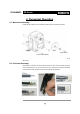
DYNAMIXEL DX-Series 1. Dynamixel DX-Series 1-1. Overview and Characteristics of the DX-Series Dynamixel DX-Series The Dynamixel robot actuator is a smart, modular actuator that incorporates a gear reducer and a control circuitry with networking functionality, all in a single package. Despite its compact size, it can produce large torque and is made with special materials to provide the necessary strength and structural resilience to withstand large external forces.
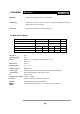
DYNAMIXEL DX-Series Metal Gear All gears are made with metal to ensure durability. Axis Bearing A bearing is used at the final axis to ensure no efficiency degradation with high external loads on the output shaft. Status LED The LED can indicate the error status to the user. 1-2. Main Specifications DX-116 DX-117 DX-113 66 66 58 142.5 192.6 192.6 Weight(g) Gear Reduction Ratio Input Voltage 12 16 12 16 12 Final Max Holding Torque(kgf.cm) 21.38 28.50 28.89 38.52 10.
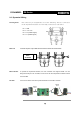
DYNAMIXEL DX-Series 2. Dynamixel Operation 2-1. Mechanical Assembly Follow the figure below for the mechanical assembly of the Dynamixel actuator. Horn Nut(8EA) Screw for Horn Screw for mount(8EA) The 8 sets of screws and nuts are only used for attaching the Dynamixel actuator to other parts. 2-2. Connector Assembly Assemble the connectors as shown below. Attach the wires to the terminals using the correct crimping tool.
DYNAMIXEL DX-Series 2-3. Dynamixel Wiring Pin Assignment The connector pin assignments are as the following. The two connectors on the Dynamixel actuator are internally connected to each other. Pin 1 : GND Pin 2 : +12V~18V Pin 4 : D- (RS485 Signal) Wire Link Connect the pins to pins that have the same number as shown below. Controller 1234 Main Main Controller Pin 4 3 4 1 Pin 1 2 3 4 Pin 3 : D+ (RS485 Signal) To operate the Dynamixel actuators, the main controller must support RS485.
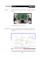
DYNAMIXEL Stand Alone DX-Series The CM-2 board can be directly mounted on a robot that is built with Dynamixel actuators. CM-2 Board on Robot For usage details, please refer to the CM-2 manual. Connection to UART To control the Dynamixel actuators, the main controller needs to convert its UART signals from TTL level to RS485 level. The recommended circuit diagram for this is shown below. 전원은 Main Controller의 Molex4P Connector의 Pin1,Pin2를 통하여 Dynamixel로 공급되어진다.
DYNAMIXEL DX-Series The direction of data signals on the TTL level TxD and RxD depends on the DIRECTION485 level as the following. • When the DIRECTION485 level is High: the TxD signal is outputted as D+, D• When the DIRECTION485 level is Low: the D+, D- signal is inputted to RxD RS485 The communication protocol used by the Dynamixel actuator, RS485 (IEEE485), uses the multi-drop method of connecting multiple terminals on a single node.
DYNAMIXEL DX-Series 3. Communication Protocol 3-1. Communication Overview Packet The Main Controller communicates with the Dynamixel by sending and receiving data packets. There are two types of packets, the Instruction Packet (Main Controller to Dynamixel) and the Status Packet.
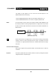
DYNAMIXEL DX-Series 3-2. Instruction Packet The structure of the Instruction Packet is as follows: Instruction Packet OXFF 0XFF ID LENGTH INSTRUCTION PARAMETER1 …PARAMETER N CHECK SUM The packet byte definitions are as follows. 0XFF 0XFF Two 0XFF bytes indicate the start of an incoming packet. ID Unique ID of a Dynamixel. The ID can range from 0X00 to 0XFD (254 IDs are available) Broadcasting ID ID ID 0XFE is the Broadcast ID which is assigned to all of the connected Dynamixel’s.
DYNAMIXEL DX-Series 0XFF 0XFF Two 0XFF bytes indicate the start of a packet. ID ID of the Dynamixel which is returning the packet. LENGTH The length of the Status Packet. The value is “Parameter number (N) + 2”. ERROR Dynamixel communication error flags. The meaning of each bit is as follows: Bit Name Details Bit 7 0 - Bit 6 Instruction Error Bit 5 Overload Error Set to 1 if the specified torque can't control the load.
DYNAMIXEL 3-4.
DYNAMIXEL Control Table DX-Series The Control Table consists of data for conditions and movement of the Dynamixel. By writing the values in the control table, you can move the Dynamixel and detect the condition of the Dynamixel. RAM and EEPROM The data values for the RAM Area will be set to the default initial values on power on. The data values for the EEPROM Area are non-volatile and will be available next power on.
DYNAMIXEL Address 0x05 DX-Series Return Delay Time. The time taken after sending the Instruction Packet, to receive the requested Status Packet. The delay time is given by 2uSec *Address5 value. Address 0x06,0x07,0x08,0x09 Operating Angle Limit. Set the operating angle to restrict the Dynamixel’s angular range. The Goal Position needs to be within the range of:CW Angle Limit <= Goal Position <= CCW Angle Limit An Angle Limit Error will occur if this relationship is not satisfied.
DYNAMIXEL DX-Series In the case of an instruction which uses the Broadcast ID (0XFE), regardless of the Address 0x10 value, the Status Packet will not be returned. Address 0X11 Alarm LED. When an Error occurs, if the corresponding Bit is set to 1, then the LED blinks.
DYNAMIXEL DX-Series From Address 0x18 in the RAM area. Address 0x18 Torque Enable. When power is first applied the Dynamixel enters the Torque Free Run condition. To allow torque to be applied Address 0x18 must be set to 1. (Torque Enabled Condition) Address 0x19 LED. LED is on when set to 1 and LED is off if set to 0. Address 0x1A~0x1D Compliance Margin and Slope. The Dynamixel controls Compliance by setting the Margin and Slope. If used well Compliance will absorb the shocks.
DYNAMIXEL Address 0x20,0x21 DX-Series Moving Speed. The angular speed to move to the Goal Position. If set to the maximum values of 0x3ff, it moves at 70RPM. Address 0x24,0x25 Present Position. Current position of the Dynamixel. Address 0x26,0x27 Present Speed. Current Speed of the Dynamixel Address 0x28,0x29 Present Load. Load size on the Dynamixel in action. Bit 10 is the direction of the load.
DYNAMIXEL Range DX-Series Each Register has an operative range. Write instructions made outside of these ranges will return an error. The following table summarises the data range for each register. 16 bit data registers are indicated as (L) and (H), two bytes. Each byte of a two byte register can be written to independently.
DYNAMIXEL DX-Series 4. Instruction Set and Examples The following Instructions are available. Value Num ber of Param eter No action. Used to obtain a Dynam ixel Status Packet. 0x01 0 READ DATA Read the values in the Control table. 0x02 2 W RITE DATA W rite the values to the Control Table. 0x03 2~ REG W RITE Sim ilar to W RITE DATA, but stay in standby m ode until write upon the action instruction. 0x04 2~ ACTION Start the action registered by REG W RITE.
DYNAMIXEL DX-Series Instruction Packet : 0XFF 0XFF 0XFE 0X04 0X03 0X03 0X01 0XF6 ID LENGTH INSTRUCTION PARAMETERS CHECKSUM Because it was transmitted by Broadcast ID(0XFE), no return status packet. 4-2.
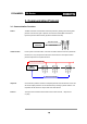
DYNAMIXEL Function DX-Series REG_WRITE instruction is similar to the WRITE_DATA instruction, but the execution timing is different. When the Instruction Packet is received the values are saved into the Buffer and the Write instruction is under a standby status. The Registered Instruction register (Address 0x2C) is set to 1. After an Action Instruction Packet is received the registered Write instruction is executed.
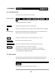
DYNAMIXEL Example 3 DX-Series To obtain the status packet of a Dynamixel with ID=1 Instruction Packet : 0XFF 0XFF 0X01 0X02 0X01 0XFB` ID LENGTH INSTRUCTION CHECKSUM The returned Status Packet is as follow; Status Packet : 0XFF 0XFF 0X01 0X02 0X00 0XFC ID LENGTH ERROR CHECKSUM 4-5. RESET Function Restore the condition of the Control Table of the Dynamixel back to the Factory Default values.
DYNAMIXEL DX-Series 5.
DYNAMIXEL DX-Series Communication ->[Dynamixel]:FF FF 00 04 03 05 02 F1 (LEN:008) <-[Dynamixel]:FF FF 00 02 00 FD (LEN:006) Status Packet Result NO ERROR The best approach is to set the Return Delay Time to the minimum value the Main Controller will allow. Example 10 Limit the the operative angles of a Dynamixel with ID=0 to 0~150°. If CCW Angle Limit is 0x3ff, it is 300°, therefore the values for 150°is 0x1ff.
DYNAMIXEL Example 13 DX-Series Make the Dynamixel with ID=0 perform only 50% of the maximum torque. Set the max torque values within the EEPROM area to 50% (0x1ff) of the maximum value (0x3ff) Instruction Packet Instruction = WRITE_DATA, Address = 0x0E, DATA = 0xff, 0x01 Communication ->[Dynamixel]:FF FF 00 05 03 0E FF 01 E9 (LEN:009) <-[Dynamixel]:FF FF 00 02 00 FD (LEN:006) Status Packet Result NO ERROR After a power off and on, you can check the effect of the changes in max torque.
DYNAMIXEL DX-Series Example 16 Turn on the LED of the Dynamixel with ID=0 and enable the torque. Instruction Packet Instruction = WRITE_DATA, Address = 0x18, DATA = 0x01, 0x01 Communication ->[Dynamixel]:FF FF 00 05 03 18 01 01 DD (LEN:009) <-[Dynamixel]:FF FF 00 02 00 FD (LEN:006) Status Packet Result NO ERROR Physical confirmation of an enabled torque can be obtained by attempting to rotate the motor with your hand.
DYNAMIXEL DX-Series C : CW Compliance Margin(Address0x01A) = 0x01(Approximately 0.29°) D : CW Compliance Slope(Address0x1C) = 0x40 (Approximately 18.
DYNAMIXEL Example 20 DX-Series Prevent the Dynamixel with ID=0 from changing values other than within the range between Address 0x18 and Address 0x23. Set Address 0x2F(Lock) to 1. Instruction Packet Instruction = WRITE_DATA, Address = 0x2F, DATA = 0x01 Communication ->[Dynamixel]:FF FF 00 04 03 2F 01 C8 (LEN:008) <-[Dynamixel]:FF FF 00 02 00 FD (LEN:006) Status Packet Result NO ERROR If Locked, it can only be unlocked by removing power.
DYNAMIXEL DX-Series Appendix RS-485 RS-485 is a protocol used for serial communication which operates by forming a bus with multiple clients connected to a single line. Thus, transmission and reception cannot occur at the same time, and while one client is transmitting, all the other clients need to be in input mode.
DYNAMIXEL DX-Series When changing the direction of RS-485, the TXD_SHIFT_REGISTER_EMPTY_BIT must be checked. The following is an example program that sends an Instruction Packet.
DYNAMIXEL DX-Series C Language Example : Dinamixel access with Atmega128 /* * The Example of Dynamixel Evaluation with Atmega128 * Date : 2004.7.20 */ #define ENABLE_BIT_DEFINITIONS //#include #include #include #include #include
DYNAMIXEL DX-Series TxDString("\r\n\n Example 4. LED OFF -- Any Key to Continue.
DYNAMIXEL DX-Series bTimeout = 0; for(bCount = 0; bCount < bRxPacketLength; bCount++) { ulCounter = 0; while(gbRxBufferReadPointer == gbRxBufferWritePointer) { if(ulCounter++ > RX_TIMEOUT_COUNT1) { bTimeout = 1; break; } } if(bTimeout) break; gbpRxBuffer[bCount] gbpRxInterruptBuffer[gbRxBufferReadPointer++]; } bLength = bCount; bChecksum = 0; /* About Register and value of bits, vide Mega128 Data Sheet.
DYNAMIXEL DX-Series Print value of Baud Rate.
DYNAMIXEL DX-Series C Language Example : Dinamixel access with Am188ER CPU #include #include #include #include #include #define MCS80 #include "..\..\base.h" #include "..\lib188es.
DYNAMIXEL DX-Series SetInterrupt(INUM_SERIAL0,Serial0Interrupt,INT_ENABLE|INT_RX, 7/*Priority*/); //Memory Initialize gbRxBufferReadPointer = gbRxBufferWritePointer = 0; STI; //Interrupt Enable /* * * Example For Driving Dynamixel DX-116 * */ TxDString("\r\n\n Dynamixel Driving Sample Program"); //Set ID to 3 bpParameter[0] = ADDRESS_ID; bpParameter[1] = 3; bPacketLength = TxPacket(bpTxBuffer, BROADCASTING_ID, INST_WRITE, bpParameter, 2/*Length of Parameter*/); bID = 3; TxDString("\r\n ->[Dynamixel]: ");
DYNAMIXEL DX-Series #define RX_TIMEOUT_COUNT2 #define RX_TIMEOUT_COUNT1 10000L //10mSec (RX_TIMEOUT_COUNT2*10L) //1Sec unsigned long ulCounter; byte bCount; ulCounter = 0; while(gbRxBufferReadPointer == gbRxBufferWritePointer) { if(ulCounter++ > RX_TIMEOUT_COUNT1) { return 0; } } bCount = 0; for(bCount = 0; bCount < 254; bCount++) //Maximum Data Length Limit : 255 { ulCounter = 0; while(gbRxBufferReadPointer == gbRxBufferWritePointer) { if(ulCounter++ > RX_TIMEOUT_COUNT2) { return bCount; } } bpRxBuffe
DYNAMIXEL DX-Series { TxD8Hex(bpPrintBuffer[bCount]); TxD8(' '); } } Result Set ID to 3 Motor Torque Enable 0xFE is BROADCAST_ID, so Dynamixel does not return status packet.
DYNAMIXEL Connector DX-Series Company Name : Molex Pin Number: 4 Model Number Male Female Molex Part Number 22-03-5045 50-37-5043 Old Part Number 5267-04 5264-04 Temperature range : -40°C to +105°C Contact Insertion Force-max : 14.7N (3.30 lb) Contact Retention Force-min : 14.7N (3.30 lb) www.molex.com or www.molex.co.jp for more detail information Female Connector Male Connector Pin No.
DYNAMIXEL DX-Series Dimension Motor Curve(No reduction gear state) 39
DYNAMIXEL DX-Series Optional Frame Application Example OF116H OF116S OF116B Body to Body Mount 40
DYNAMIXEL DX-Series Full Option frame The CM-2 Board - A dedicated board designed for controlling Dynamixel actuators - Available optional parts: Blue-tooth module, RS232 UART, and 6-button blue-tooth remote controller - Can be directly mounted on a multi-degrees of freedom robot.
DYNAMIXEL DX-Series Dynamixel Application Example CYCLOIDⅡ 42