User’s Manual 2004-04-02 Closer to Real, Dynamixel DX-116
DYNAMIXEL DX-116 Contents 1. Summary 1-1. Overview & Characteristics of DX-116 Page 2 1-2. Main Specification Page 4 2. Dynamixel Assembly 2-1. Mechanical Parts Assembly Page 5 2-2. Connector Assembly Page 5 2-3. Dynamixel Wiring Page 6 3. Communication Protocol 3-1. Communication Overview Page 9 3-2. Instruction Packet Page 10 3-3. Status Packet Page 10 3-4. Control Table Page 13 4. Instruction Set and Examples 4-1. WRITE _DATA Page 20 4-2. READ _DATA Page 21 4-3.
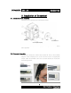
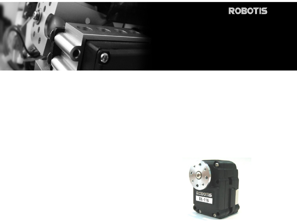
DYNAMIXEL DX-116 1. Dynamixel DX-116 1-1. Overview & Characteristics of DX-116 Dynamixel DX-116 The Dynamixel is a smart actuator which incorporates a precision servo motor and a control unit with networking functionality, all in a single unit. Despite its compact size, it can produce high torque and has been manufactured using high quality materials to provide the necessary strength and structural resilience. It can also detect and act upon internal conditions such as temperature and over-current .
DYNAMIXEL DX-116 Metal Gears All the gear sets are made of metal to ensure extreme durability. Axis Bearing A bearing is used on the final axis to ensure there is no loss of efficiency during heavily loaded conditions. Status LED A LED indicates error status. 3 English Translation by: Tribotix Pty Ltd www.tribotix.
DYNAMIXEL DX-116 1-2. Main Specification Holding Torque 31.5kg·cm (18V) ~ 21 kg·cm (12V) Reduction ratio 1/140 Speed 0.084sec/60° (18V) ~ 0.125sec/60° (12V) Resolution 0.35° Operating Angle 300° Voltage 12V~18V (Recommended voltage: 14~15V) Max. Current 1200mA Operating Temp.
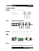
DYNAMIXEL DX-116 2. Installation of Dynamixel 2-1. Mechanical Parts Assembly Mechanical Parts of Dynamixel are assembled as follows: Horn Nut(8EA) Screw for Horn Screw for mount(8EA) The 8 sets of Nuts & Screws are only used when a Dynamixel is mounted to other equipment. 2-2. Connector Assembly Assemble the connectors as shown below. Attach the wires to the terminals using the correct crimping tool.
DYNAMIXEL DX-116 2-3. Wiring of Dynamixel Pin Assignment Pin assignments of the connectors are as follows:- Pin 1: GND Pin 2: +12V~18V Pin 4: D- (RS485 Signal) Connect the same pin numbers as shown below. Main Controller Main Controller 4 3 2 1 Wire Link Pin 4 3 2 1 Pin 1 2 3 4 Pin 3: D+ (RS485 Signal) The Main Controller must support RS485 to control the Dynamixel. A proprietary Controller may be utilised but the Cycloid-M2 board is recommended.
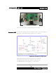
DYNAMIXEL DX-116 Cycloid-M2 Board on Robot Please refer to the Cycloid-M2 Board manual for more details. Connection to UART To control the Dynamixel, the main Controller needs to convert the signals to RS485. The recommended schematic configuration is as follows:- 전원은 Main Controller의 Molex4P Connector의 Pin1,Pin2를 통하여 Dynamixel로 공급되어진다.
DYNAMIXEL DX-116 RS485 A multi-dropped RS485 (IEEE485) network is established from the main controller. Data Packets are then issued through this single portal. Main Controller [RS485 Multi Drop Link] Please note that caution should be applied when connecting the Dynamixel units to ensure that the pin assignments are correct. Always check the current consumption. The standby current consumption of a Dynamixel unit should be less than 50mA.
DYNAMIXEL DX-116 3. Communication Protocol 3-1. Communication Overview Packet The Main Controller communicates with the Dynamixel by sending and receiving data packets.
DYNAMIXEL DX-116 3-2. Instruction Packet The structure of the Instruction Packet is as follows: Instruction Packet OXFF 0XFF ID LENGTH INSTRUCTION PARAMETER1 …PARAMETER N CHECK SUM The packet byte definitions are as follows:- 0XFF 0XFF Two 0XFF bytes indicate the start of an incoming packet. ID Unique ID of a Dynamixel. The ID can range from 0X00 to 0XFD (254 IDs are available) Broadcasting ID ID 0XFE is the Broadcast ID which is assigned to all of the connected Dynamixel’s.
DYNAMIXEL DX-116 OXFF 0XFF ID LENGTH ERROR PARAMETER1 PARAMETER2…PARAMETER N CHECK SUM The meaning of each byte within the packet is as follows:- 0XFF 0XFF Two 0XFF bytes indicate the start of a packet ID ID of the Dynamixel which is returning the packet. LENGTH The length of the Status Packet. The value is “Parameter number (N) + 2”. ERROR Dynamixel communication error flags.
DYNAMIXEL DX-116 3-4.
DYNAMIXEL DX-116 Control Table The Control Table consists of data for conditions and movement of the Dynamixel. By writing the values in the control table, you can move the Dynamixel and detect the condition of the Dynamixel. RAM and EEPROM The data values for the RAM Area will be set to the default initial values on power on. The data values for the EEPROM Area are non-volatile and will be available next power on.
DYNAMIXEL DX-116 receive the requested Status Packet. The delay time is given by 2uSec * Address5 value. Address 0x06,0x07,0x08,0x09 Operating Angle Limit. Set the operating angle to restrict the Dynamixel’s angular range. The Goal Position needs to be within the range of:CW Angle Limit <= Goal Position <= CCW Angle Limit An Angle Limit Error will occur if this relationship is not satisfied. Address 0x0B the Highest Limit Temperature. The upper limit of the Dynamixel’s operative temperature.
DYNAMIXEL DX-116 Address 0X11 Alarm LED. When an Error occurs, if the corresponding Bit is set to 1, then the LED blinks.
DYNAMIXEL DX-116 From Address 0x18 in the RAM area. Address 0x18 Torque Enable. When power is first applied the Dynamixel enters the Torque Free Run condition. To allow torque to be applied Address 0x18 must be set to 1. (Torque Enabled Condition) Address 0x19 LED is on when set to 1 and LED is off if set to 0. Address 0x1A~0x1D Compliance Margin and Slope. The Dynamixel controls Compliance by setting the Margin and Slope. If used well Compliance will absorb the shocks.
DYNAMIXEL DX-116 150° (Goal Position = 0x1ff) 300° (Goal Position = 0x3ff) 330~360° Invalid Angle Address 0x20,0x21 0° (Goal Position = 0) Moving Speed. The angular speed to move to the Goal Position. If set to the maximum values of 0x3ff, it moves at 70RPM. Address 0x24,0x25 Present Position. Current position of the Dynamixel. Address 0x26,0x27 Present Speed. Current Speed of the Dynamixel. Address 0x28,0x29 Present Load. Load size on the Dynamixel in action.
DYNAMIXEL DX-116 Address 0x2F Lock. If set to 1, only Address 0x18 ~ Address 0x23 can be written to. Other areas are not permitted. Once locked, it can only be unlocked by powering down. Address 0x30,0x31 Punch. Minimum current being supplied to the motor during an action. The minimum value is 0x20 and the maximum value as 0x3ff. Range Each Register has an operative range. Write instructions made outside of these ranges will return an error.
DYNAMIXEL DX-116 4. Instruction Set and Examples The following Instructions are available. Ins tr uc tion Na me Va lue Numbe r of P arame te r No a c tion. Us e d to obta in a Dyna mix e l Sta tus Pa c ke t. 0x 01 0 Re a d the va lue s in the Contr ol T a ble . 0x 02 2 WRIT E_DAT A Wr ite the va lue s to the Contr ol T a ble . 0x 03 2 ~ Simila r to WRIT E_DAT A, but s ta y in s ta ndby mode until the wr ite upon the a c tion ins tr uc tion.
DYNAMIXEL DX-116 Broadcasting ID (0xFE). Instruction Packet : 0XFF 0XFF 0XFE 0X04 0X03 0X03 0X01 0XF6` ID LENGTH INSTRUCTION PARAMETERS CHECKSUM Because it was transmitted by Broadcast ID(0XFE), no return status packet. 4-2. READ_DATA Function Read data from the Control Table of Dynamixel. Length 0X04 Instruction 0X02 Parameter1 Starting Address of Data to Read Parameter2 length of Data to Read Example 2 Read the internal temperature of the Dynamixel with ID=1.
DYNAMIXEL DX-116 Function REG_WRITE instruction is similar to the WRITE_DATA instruction, but the execution timing is different. When the Instruction Packet is received the values are saved into the Buffer and the Write instruction is under a standby status. The Registered Instruction register (Address 0x2C) is set to 1. After an Action Instruction Packet is received the registered Write instruction is executed.
DYNAMIXEL DX-116 Example 3 To obtain the status packet of a Dynamixel with ID=1 Instruction Packet : 0XFF 0XFF 0X01 0X02 0X01 0XFB` ID LENGTH INSTRUCTION CHECKSUM The returned Status Packet is as follow; Status Packet : 0XFF 0XFF 0X01 0X02 0X00 0XFC ID LENGTH ERROR CHECKSUM 4-5. RESET Function Restore the condition of the Control Table of the Dynamixel back to the Factory Default values.
DYNAMIXEL DX-116 5.
DYNAMIXEL DX-116 The best approach is to set the Return Delay Time to the minimum value the Main Controller will allow. Example 9 Limit the the operative angles of a Dynamixel with ID=0 to 0~150°. If CCW Angle Limit is 0x3ff, it is 300°, therefore the values for 150°is 0x1ff.
DYNAMIXEL DX-116 Instruction Packet Instruction = WRITE_DATA, Address = 0x0E, DATA = 0xff, 0x01 Communication ->[Dynamixel]:FF FF 00 05 03 0E FF 01 E9 (LEN:009) <-[Dynamixel]:FF FF 00 02 00 FD (LEN:006) Status Packet Result NO ERROR After a power off and on, you can check the effect of the changes in max torque. Example 13 Stop the Dynamixel with ID=0 from returning a Status Packet.
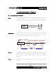
DYNAMIXEL DX-116 Example 16 Set the Dynamixel with ID=0 to have a Compliance Margin = 1 and Compliance Slope=0x40 The following graph shows the Angle Error and Torque Output. CW Goal Position CCW CW X:Angle Error CCW If the position is slightly deviated from the goal position, the motor will generate a high torque to try to adjust its position to that of the goal position. The true control method is different due to the inertia.
DYNAMIXEL DX-116 number), that is, the effect of the values of Compliance between 0x11 and 0x20 are the same. Example 17 Position Dynamixel with ID=0 at Position 180°after moving it at the speed of 35RPM.
DYNAMIXEL DX-116 Instruction Packet Instruction = WRITE_DATA, Address = 0x2F, DATA = 0x01 Communication ->[Dynamixel]:FF FF 00 04 03 2F 01 C8 (LEN:008) <-[Dynamixel]:FF FF 00 02 00 FD (LEN:006) Status Packet Result NO ERROR If Locked, it can only be unlocked by removing power. If trying to access other data areas whilst locked, an error will be returned.
DYNAMIXEL DX-116 Appendix RS485 Direction The Main Controller sets the RS485 communication direction to be an input at all times other than when specifically sending an instruction packet. RS485 Direction Output Duration Instruction Packet Status Packet Return Delay Time Return Delay Time The Default Value is 160us and can be changed via the Control Table at Address 0x05.
DYNAMIXEL DX-116 TXD_SHIFT_REGISTER_EMPTY_BIT.
DYNAMIXEL DX-116 C Language Example #include #include #include #include #include #define MCS80 #include "..\..\base.h" #include "..\lib188es.
DYNAMIXEL DX-116 SetInterrupt(INUM_SERIAL0,Serial0Interrupt,INT_ENABLE|INT_RX, 7/*Priority*/); //Memory Initialize gbRxBufferReadPointer = gbRxBufferWritePointer = 0; STI; //Interrupt Enable /* * * Example For Driving Dynamixel DX-116 * */ TxDString("\r\n\n Dynamixel Driving Sample Program"); //Set ID to 3 bpParameter[0] = ADDRESS_ID; bpParameter[1] = 3; bPacketLength = TxPacket(bpTxBuffer, BROADCASTING_ID, INST_WRITE, bpParameter, 2/*Length of Parameter*/); bID = 3; TxDString("\r\n ->[Dynamixel]: "); Prin
DYNAMIXEL DX-116 #define RX_TIMEOUT_COUNT2 #define RX_TIMEOUT_COUNT1 10000L //10mSec (RX_TIMEOUT_COUNT2*10L) //1Sec unsigned long ulCounter; byte bCount; ulCounter = 0; while(gbRxBufferReadPointer == gbRxBufferWritePointer) { if(ulCounter++ > RX_TIMEOUT_COUNT1) { return 0; } } bCount = 0; for(bCount = 0; bCount < 254; bCount++) //Maximum Data Length Limit : 255 { ulCounter = 0; while(gbRxBufferReadPointer == gbRxBufferWritePointer) { if(ulCounter++ > RX_TIMEOUT_COUNT2) { return bCount; } } bpRxBuffer[bCo
DYNAMIXEL DX-116 { TxD8Hex(bpPrintBuffer[bCount]); TxD8(' '); } } Result Set ID to 3 Motor Torque Enable 0xFE is BROADCAST_ID, so Dynamixel does not return status packet.(First 2 Instruction Packet) 34 English Translation by: Tribotix Pty Ltd www.tribotix.
DYNAMIXEL DX-116 Connector Company Name : Molex Pin Number: 4 Model Number Male Female Molex Part Number 22-03-5045 50-37-5043 Old Part Number 5267-04 5264-04 Temperature range : -40°C to +105°C Contact Insertion Force-max : 14.7N (3.30 lb) Contact Retention Force-min : 14.7N (3.30 lb) www.molex.com or www.molex.co.jp for more detail information Female Connector Male Connector Pin No.1 35 English Translation by: Tribotix Pty Ltd www.tribotix.
DYNAMIXEL DX-116 Dimension Motor Curve(No reduction gear state) 36 English Translation by: Tribotix Pty Ltd www.tribotix.
DYNAMIXEL DX-116 Optional Frame Application Example OF116H OF116S OF116B Body to Body Mount 37 English Translation by: Tribotix Pty Ltd www.tribotix.
DYNAMIXEL DX-116 Full Option frame 23Axis frame full Set 15Axis frame full set Helmet and hands plastic is not included in frame set Cycloid M2 Board - The Custom-Built Controller for Dynamixel - Optional Part : Blue-tooth module, RS232 UART, and 6-button blue-tooth remocon. - Can be adapted multi-axis robot directly. 86 48 38 English Translation by: Tribotix Pty Ltd www.tribotix.
DYNAMIXEL DX-116 Application Example CYCLOIDⅡ 39 English Translation by: Tribotix Pty Ltd www.tribotix.