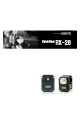
User’s Manual 2007-03-27 Closer to Real, Dynamixel RX-28
DYNAMIXEL RX-28 Contents 1. Summary 1-1. Overview and Characteristics of RX-28 Page 2 1-2. Main Specifications Page 3 2. Dynamixel Operation 2-1. Mechanical Assembly Page 4 2-2. Connector Assembly Page 5 2-3. Dynamixel Wiring Page 6 3. Communication Protocol 3-1. Communication Overview Page 9 3-2. Instruction Packet Page 10 3-3. Status Packet Page 10 3-4. Control Table Page 12 4. Instruction Set and Examples 4-1. WRITE_DATA Page 19 4-2. READ_DATA Page 20 4-3.
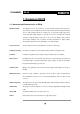
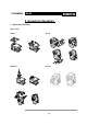
DYNAMIXEL RX-28 1. Dynamixel RX-28 1-1. Overview and Characteristics of RX-28 Dynamixel RX-28 The Dynamixel series robot actuator is a smart, modular actuator that incorporates a gear reducer, a precision DC motor and a control circuitry with networking functionality, all in a single package. Despite its compact size, it can produce high torque and is made with high quality materials to provide the necessary strength and structural resilience to withstand large external forces.
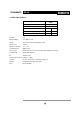
DYNAMIXEL RX-28 1-2. Main Specifications RX-28 Weight (g) 72 Gear Reduction Ratio 1/193 Input Voltage (V) at 12V at 16V Final Max Holding Torque(kgf.cm) 28.3 37.7 Sec/60degree 0.167 0.126 Resolution 0.3° Operating Angle 300°, Endless Turn Voltage 12V~16V (Recommended voltage: 14.4V) Max.
DYNAMIXEL RX-28 2. Dynamixel Operation 2-1.
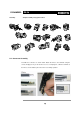
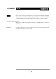
DYNAMIXEL Assembly RX-28 Sample assembly using option frames. 2-2 . Connector Assembly Assemble the connectors as shown below. Attach the wires to the terminals using the correct crimping tool. If you do not have access to a crimping tool, solder the terminals to the wires to ensure that they do not become loose during operation.
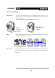
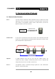
DYNAMIXEL RX-28 2-3. Dynamixel Wiring Pin Assignment The connector pin assignments are as the following. The two connectors on the Dynamixel are connected pin to pin, thus the RX-28 can be operated with only one connector attached. ( Note : The pin number of connector’s edge cut side is PIN1) PIN1: GND PIN2: VDD(12V~21V) PIN3: D+ PIN4: D- PIN4: DPIN3: D+ PIN2: VDD(12V~21V) PIN1: GND Wiring Connect the RX-28 actuators pin to pin as shown below.
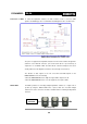
DYNAMIXEL Connection to UART RX-28 To control the Dynamixel actuators, the main controller needs to convert its UART signals to the RS485 type. The recommended circuit diagram for this is shown below.\ CCW VDD VDD The power is supplied to the Dynamixel actuator from the main controller through Pin 1 and Pin 2 of the Molex3P connector. (The circuit shown above is presented only to explain the use of RS485 UART.
DYNAMIXEL Caution RX-28 Please ensure that the pin assignments are correct when connecting the Dynamixel actuators. Check the current consumption when powering on. The current consumption of a single Dynamixel actuator unit in standby mode should be no larger than 50mA Connection Status Verification When power is applied to the Dynamixel actuator, the LED blinks twice to confirm its connection.
DYNAMIXEL RX-28 3. Communication Protocol 3-1. Communication Overview Packet The main controller communicates with the Dynamixel units by sending and receiving data packets. There are two types of packets; the “Instruction Packet” (sent from the main controller to the Dynamixel actuators) and the “Status Packet” (sent from the Dynamixel actuators to the main controller.
DYNAMIXEL RX-28 3-2. Instruction Packet The Instruction Packet is the packet sent by the main controller to the Dynamixel units to send commands. The structure of the Instruction Packet is as the following. Instruction Packet OXFF 0XFF ID LENGTH INSTRUCTION PARAMETER1 …PARAMETER N CHECK SUM The meanings of each packet byte definition are as the following. 0XFF 0XFF The two 0XFF bytes indicate the start of an incoming packet. ID The unique ID of a Dynamixel unit.
DYNAMIXEL RX-28 The meanings of each packet byte definition are as the following. 0XFF 0XFF The two 0XFF bytes indicate the start of the packet. ID The unique ID of the Dynamixel unit returning the packet. The initial value is set to 1. LENGTH The length of the packet where its value is “Number of parameters (N) + 2” ERROR The byte representing errors sent from the Dynamixel unit. The meaning of each bit is as the following.
DYNAMIXEL 3-4.
DYNAMIXEL Control Table RX-28 The Control Table contains information on the status and operation of the Dynamixel actuator. The Dynamixel actuator is operated by writing values to its control table and its status is checked by reading values off its control table. RAM and EEPROM The data values for the RAM area will be set to the default initial values whenever the power is turned on. However, the data values for the EEPROM area are non-volatile and will still remain even after the power is turned off.
DYNAMIXEL Address 0x05 RX-28 Return Delay Time. The time it takes for the Status Packet to return after the Instruction Packet is sent. The delay time is given by 2uSec * Address5 value. Address 0x06,0x07,0x08,0x09 Operating Angle Limit. Sets the Dynamixel actuator’s operating angle range. The Goal Position needs to be within the range of: CW Angle Limit <= Goal Position <= CCW Angle Limit. An Angle Limit Error will occur if the Goal Position is set outside this range set by the operating angle limits.
DYNAMIXEL RX-28 In the case of an instruction which uses the Broadcast ID (0XFE) the Status Packet will not be returned regardless of the Address 0x10 value. Address 0X11 Alarm LED. If the corresponding Bit is set to 1, the LED blinks when an Error occurs.
DYNAMIXEL Address 0x18 RX-28 Torque Enable. When the power is first turned on, the Dynamixel actuator enters the Torque Free Run condition (zero torque). Setting the value in Address 0x18 to 1 enables the torque. Address 0x19 LED. The LED turns on when set to 1 and turns off if set to 0. Address 0x1A~0x1D Compliance Margin and Slope. The compliance of the Dynamixel actuator is defined by setting the compliance Margin and Slope. This feature can be utilized for absorbing shocks at the output shaft.
DYNAMIXEL Address 0x20,0x21 RX-28 Moving Speed. Sets the angular velocity of the output moving to the Goal Position. Setting this value to its maximum value of 0x3ff moves the output with the maximum angular velocity which depends on the level of power supplied and Dynamixel series. (The lowest velocity is when this value is set to 1. When set to 0, the velocity is the largest possible for the supplied voltage, e.g. no velocity control is applied.) Address 0x24,0x25 Present Position.
DYNAMIXEL RX-28 Goal Speed Setting BIT 15~11 10 Value 0 Turn Direction 9 7 6 5 4 3 2 1 0 Speed Value Turn Direction = 0 : CCW Direction Turn, Range 8 Load Direction = 1: CW Direction Turn Each data has a valid minimum and maximum values. Write instructions made outside of these valid ranges will return an error. The following table summarizes the data range for each register. 16 bit data registers are indicated with two bytes (L) and (H).
DYNAMIXEL RX-28 4. Instruction Set and Examples The following Instructions are available. Value Num ber of Param eter No action.
DYNAMIXEL RX-28 Instruction Packet : 0XFF 0XFF 0XFE 0X04 0X03 0X03 0X01 0XF6` ID LENGTH INSTRUCTION PARAMETERS CHECKSUM Because it was transmitted with a Broadcast ID (0XFE), no status packets are returned. 4-2.
DYNAMIXEL RX-28 4-3. REG_WRITE과 ACTION 4-3-1. REG_WRITE Function The REG_WRITE instruction is similar to the WRITE_DATA instruction, but the execution timing is different. When the Instruction Packet is received the values are stored in the Buffer and the Write instruction is under a standby status. At this time, the Registered Instruction register (Address 0x2C) is set to 1. After the Action Instruction Packet is received, the registered Write instruction is finally executed.
DYNAMIXEL RX-28 4-4. PING Function Does not command any operations. Used for requesting a status packet or to check the existence of a Dynamixel actuator with a specific ID.
DYNAMIXEL RX-28 The returned Status Packet is as the following Status Packet : 0XFF 0XFF 0X00 0X02 0X00 0XFD ID LENGTH ERROR CHECKSUM Note the ID of this Dynamixel actuator is now changed to 1 after the RESET instruction. 4-6. SYNC WRITE Function Used for controlling many Dynamixel actuators at the same time. The communication time decreases by the Synch Write instruction since many instructions can be transmitted by a single instruction.
DYNAMIXEL RX-28 Dynamixel actuator with an ID of 2: to position 0X030 with a speed of 0X170 Dynamixel actuator with an ID of 0: to position 0X220 with a speed of 0X380 Instruction Packet : 0XFF 0XFF 0XFE 0X18 0X83 0X1E 0X04 0X00 0X10 0X00 0X50 0X01 0X01 0X20 0X02 0X60 0X03 0X02 0X30 0X00 0X70 0X01 0X03 0X20 0X02 0X80 0X03 0X12 No status packets are returned since the Broadcasting ID was used.
DYNAMIXEL RX-28 5. Example For the following examples, we assume a Dynamixel actuator with an ID of 1 in Reset status and that the Baud rate is 57142 BPS.
DYNAMIXEL RX-28 Instruction Packet Instruction = WRITE_DATA, Address = 0x05, DATA = 0x02 Communication ->[Dynamixel]:FF FF 00 04 03 05 02 F1 (LEN:008) <-[Dynamixel]:FF FF 00 02 00 FD (LEN:006) Status Packet Result NO ERROR It is recommended to set the Return Delay Time to the minimum value allowed by the Main Controller.
DYNAMIXEL Example 13 RX-28 Setting the maximum torque to 50% of its maximum possible value for a Dynamixel actuator with an ID of 0 Set the MAX Torque value located in the ROM area to 0x1ff which is 50% of the maximum value 0x3ff.
DYNAMIXEL RX-28 Instruction Packet Instruction = WRITE_DATA, Address = 0x18, DATA = 0x01, 0x01 Communication ->[Dynamixel]:FF FF 00 05 03 18 01 01 DD (LEN:009) <-[Dynamixel]:FF FF 00 02 00 FD (LEN:006) Status Packet Result NO ERROR You can verify the Torque Enabled status by trying to move the output of the actuator by hand.
DYNAMIXEL Instruction Packet RX-28 D : CW Compliance Slope (Address0x1C) = 0x40 (about 18.8°) Instruction = WRITE_DATA, Address = 0x1A, DATA = 0x01, 0x01, 0x40, 0x40 Communication ->[Dynamixel]:FF FF 00 07 03 1A 01 01 40 40 59 (LEN:011) <-[Dynamixel]:FF FF 00 02 00 FD (LEN:006) Status Packet Result NO ERROR The Compliance Slope takes effect with discrete steps of 2n (n is integer). Thus any Compliance value between 0x11 and 0x20 has identical effects.
DYNAMIXEL RX-28 Status Packet Result NO ERROR Example 20 Lock all addresses except for Address 0x18 ~ Address0x23 for a Dynamixel actuator with an ID of 0 Set Address 0x2F (Lock) to 1. Instruction Packet Instruction = WRITE_DATA, Address = 0x2F, DATA = 0x01 Communication ->[Dynamixel]:FF FF 00 04 03 2F 01 C8 (LEN:008) <-[Dynamixel]:FF FF 00 02 00 FD (LEN:006) Status Packet Result NO ERROR Once locked, the only way to unlock it is to remove the power.
DYNAMIXEL RX-28 Appendix RS485 UART RS485 UART is a serial communication protocol where both TxD and RxD cannot be used at the same time. This method is generally used when many devices need to be connected to a single bus. Since more than one device are connected to the same bus, all the other devices need to be in input mode while one device is transmitting.
DYNAMIXEL RX-28 When changing the direction, the TXD_SHIFT_REGISTER_EMPTY_BIT must be checked. The following is an example program that sends an Instruction Packet.
DYNAMIXEL RX-28 C Language Example : Dinamixel access with Atmega128 /* * The Example of Dynamixel Evaluation with Atmega128 * Date : 2005.5.11 * Author : BS KIM */ /* * included files */ #define ENABLE_BIT_DEFINITIONS //#include #include #include #include #include
DYNAMIXEL RX-28 // --- Gloval Variable Number --volatile byte gbpRxInterruptBuffer[256]; byte gbpParameter[128]; byte gbRxBufferReadPointer; byte gbpRxBuffer[128]; byte gbpTxBuffer[128]; volatile byte gbRxBufferWritePointer; TxDString("\r\n\n Example 4. LED OFF -- Any Key to Continue.
DYNAMIXEL RX-28 while(1); } bTimeout = 0; for(bCount = 0; bCount < bRxPacketLength; bCount++) { ulCounter = 0; while(gbRxBufferReadPointer == gbRxBufferWritePointer) { if(ulCounter++ > RX_TIMEOUT_COUNT1) { bTimeout = 1; break; } } if(bTimeout) break; gbpRxBuffer[bCount] = gbpRxInterruptBuffer[gbRxBufferReadPointer++]; } bLength = bCount; bChecksum = 0; void PortInitialize(void) { DDRA = DDRB = DDRC = DDRD = DDRE = DDRF = 0; //Set all port to input direction first.
DYNAMIXEL RX-28 } /* Print value of Baud Rate.
DYNAMIXEL Connector RX-28 Company Name : Molex Pin Number: 4 (or 5 for Optional VCC 5V) Model Number Male Female Molex Part Number 22-03-5045 50-37-5043 Old Part Number 5267-04 5264-04 Temperature range : -40°C to +105°C Contact Insertion Force-max : 14.7N (3.30 lb) Contact Retention Force-min : 14.7N (3.30 lb) www.molex.com or www.molex.co.jp for more detail information Female Connector Male Connector Pin No.
DYNAMIXEL RX-28 Dimension 38