
Data Sheet

2/22/2018 XM540-W150
http://support.robotis.com/en/product/actuator/dynamixel_x/xm_series/xm540-w150.htm 9/17
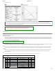
0 PING Instruction Status Packet will not be returned for all Instructions. (Exception : PING Instruction)
1
PING Instruction
READ Instruction
Status Packet will only be returned for READ Instruction.
exceptionally returns Status Packet to all Instruction.
2 All Instructions Status Packet will be returned for all Instructions.
Note : If the ID of Instruction Packet is set to Broad Cast ID(0xFE), Status Packet will not be returned for READ and WRITE Instructions regardless of Status Return Level(68). For more details, please
refer to the Protocol section of e-Manual
Registered Instruction (69)
This value will be set to ‘1’ when Dynamixel receives REG_WRITE Instruction Packet while processing ACTION Instruction Packet will clear this value to ‘0’.
Hardware Error Status (70)
This value indicates hardware error status. For more details, please refer to the Shutdown(63).
Velocity I Gain (76), Velocity P Gain (78)
These values indicate Gains of Velocity Control Mode. Gains of Dynamixel’s internal controller can be calculated from Gains of the Control Table as shown below. The constant in each equations include
sampling time. Velocity P Gain of Dynamixel’s internal controller is abbreviated to K
V
P and that of the Control Table is abbreviated to K
V
P
(TBL)
.
Controller Gain Conversion Equations Range Description
Velocity I Gain(76)
K
V
I K
V
I = K
V
I
(TBL)
/ 65,536
0 ~ 16,383 I Gain
Velocity P Gain(78)
K
V
P K
V
P = K
V
P
(TBL)
/ 128
0 ~ 16,383 P Gain
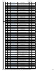
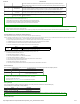
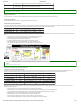
Below figure is a block diagram describing the velocity controller in Velocity Control Mode. When the instruction transmitted from the user is received by Dynamixel, it takes following steps until driving the
horn.
① An Instruction from the user is transmitted via Dynamixel bus, then registered to Goal Velocity(104).
② Goal Velocity(104) is converted to target velocity trajectory by Profile Acceleration(108).
③ The target velocity trajectory is stored at Velocity Trajectory(136).
④ PI controller calculates PWM output for the motor based on the target velocity trajectory.
⑤ Goal PWM(100) sets a limit on the calculated PWM output and decides the final PWM value.
⑥ The final PWM value is applied to the motor through an Inverter, and the horn of Dynamixel is driven.
⑦ Results are stored at Present Position(132), Present Velocity(128), Present PWM(124) and Present Current(126).
Note : K
a
stands for Anti-windup Gain and ‘β’ is a conversion coefficient of position and velocity that cannot be modified by users. For more details about the PID controller, please refer to the below
website.
http://en.wikipedia.org/wiki/PID_controller
Position D Gain (80), Position I Gain (82), Position P Gain (84)
Feedforward 2nd Gain (88), Feedforward 1st Gain (90)
These Gains are used in Position Control Mode and Extended Position Control Mode. Gains of Dynamixel’s internal controller can be calculated from Gains of the Control Table as shown below. The
constant in each equations include sampling time. Position P Gain of Dynamixel’s internal controller is abbreviated to K
P
P and that of the Control Table is abbreviated to K
P
P
(TBL)
.
Controller Gain Conversion Equation Range Description
Position D Gain(76)
K
P
D K
P
D = K
P
D
(TBL)
/ 16
0 ~ 16,383 D Gain
Position I Gain(76)
K
P
I K
P
I = K
P
I
(TBL)
/ 65,536
0 ~ 16,383 I Gain
Position P Gain(78)
K
P
P K
P
P = K
P
P
(TBL)
/ 128
0 ~ 16,383 P Gain
Feedforward 2nd Gain(88)
K
FF2nd
K
FF2nd
= K
FF2nd(TBL)
/ 4
0 ~ 16,383 Feedforward Acceleration Gain
Feedforward 1st Gain(90)
K
FF1st
KFF1st = K
FF1st(TBL)
/ 4
0 ~ 16,383 Feedforward Velocity Gain
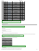
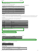
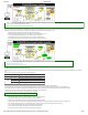
Below figure is a block diagram describing the position controller in Position Control Mode and Extended Position Control Mode. When the instruction from the user is received by Dynamixel, it takes
following steps until driving the horn.
① An Instruction from the user is transmitted via Dynamixel bus, then registered to Goal Position(116).
② Goal Position(116) is converted to target position trajectory and target velocity trajectory by Profile Velocity(112) and Profile Acceleration(108).
③ The target position trajectory and target velocity trajectory is stored at Position Trajectory(140) and Velocity Trajectory(136) respectively.
④ Feedforward and PID controller calculate PWM output for the motor based on target trajectories.
⑤ Goal PWM(100) sets a limit on the calculated PWM output and decides the final PWM value.
⑥ The final PWM value is applied to the motor through an Inverter, and the horn of Dynamixel is driven.
⑦ Results are stored at Present Position(132), Present Velocity(128), Present PWM(124) and Present Current(126).