
Data Sheet
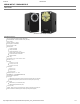

2/23/2018 XM540-W270
http://support.robotis.com/en/product/actuator/dynamixel_x/xm_series/xm540-w270.htm 6/17
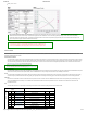
This mode is identical to the Joint Mode from existing Dynamixels. Operating position range is limited by Max Position Limit(48) and Min
Position Limit(52). This mode is ideal for articulated robots that each joint rotates less than 360 degrees.
4
Extended Position
Control Mode(Multi-turn)
This mode controls position.
This mode is identical to the Multi-Turn Mode from existing Dynamixels. 512 turns are supported(-256[rev] ~ 256[rev]).
This mode is ideal for multi-turn wrists or conveyer systems or a system that requires an additional reduction gear.
5
Current-based Position
Control Mode
This mode controls both position and current(torque). Up to 512 turns are supported(-256[rev] ~ 256[rev]).
This mode is ideal for a system that requires both position and current control such as articulated robots or grippers.
16
PWM Control Mode
(Voltage Control Mode)
This mode directly controls PWM output.
(Voltage Control Mode)
Note : Switching Operating Mode will reset gains(PID, Feedfoward) properly to the selected Operating Mode. The profile generator and limits will also be reset.
① Profile Velocity(112), Profile Acceleration(108) : Reset to ‘0’
② Goal PWM(100), Goal Current(102) : Reset to PWM Limit(36), Current Limit(38) respectively
③ Current-based Position Control Mode : Reset to Position Gain(PID) and PWM Limit(36) values
Changed Position Gain(PID) and PWM Limit(36) values can be read from the Control Table.
Note : PWM is the abbreviation for Pulse Width Modulation that modulates PWM Duty to control motors. The PWM Control Mode changes pulse width to control average supply voltage to the motor
and this technique is widely used in the motor control field.
Therefore, PWM Control Mode uses Goal PWM(100) value to control supply voltage for Dynamixel. PWM Control Mode is similar to the Wheel Mode of Dynamixel AX and RX series.
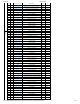
Secondary(Shadow) ID (12, Available from Firmware Version 38)
Set the Dynamixel’s Secondary ID. Secondary ID(12) is a value to identify each Dynamixel, just like ID(7).
However, unlike ID(7), Secondary ID(12) is not a unique value. Therefore, Dynamixels with the same Secondary ID value form a group. The differences between Secondary ID(12) and ID(7) are as follows :
① Secondary ID(12) is not a unique value. i.e., a lot of Dynamixels may have the same Secondary ID value.
② ID(7) has a higher priority than Secondary ID(12). i.e., if Secondary ID(12) and ID(7) are the same, ID(7) will be applied first.
③ The EEPROM area of the Control Table cannot be modified with Secondary ID(12). Only the RAM area can be modified.
④ If Instruction Packet ID is the same as Secondary ID(12), the Status Packet will not be returned.
⑤ If the value of Secondary ID(12) is 253 or higher, the Secondary ID function is deactivated.
Values Description
Range
0 ~ 252
253 ~ 255
Activate Secondary ID function
Deactivate Secondary ID function, Default value ‘255’
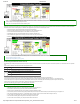
The following are examples of operation when there are five Dynamixels with ID (7) set from 1 to 5.
① Set all five Dynamixels' Secondary ID(12) to '5'.
② Send Write Instruction Packet(ID = 1, LED(65) = 1).
③ Turn on LED of Dynamixel with ID '1' and return the Status Packet.
④ Send Write Instruction Packet(ID = 5, LED(65) = 1).
⑤ Turn on LED on five Dynamixels. However, Status Packet of Dynamixel with ID ‘5’ will be returned.
⑥ Set the Secondary ID(12) of all five Dynamixels to ‘100’.
⑦ Send Write Instruction Packet(ID = 100, LED(65) = 0).
⑧ Turn off LED on five Dynamixels. However, as there is no Dynamixel with ID ‘100’, Status Packet is not returned.
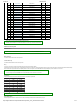
Protocol version (13)
Users can select Dynamixel protocol version (1.0 and 2.0). It is recommended to use an identical protocol version for multiple Dynamixels.
Protocol Version Compatible Dynamixels
1 1.0 AX, DX, RX, MX, EX Series
2(Default) 2.0
MX Series (MX-28, MX-64, MX-106 with FW V39 or above),
X Series, Dynamixel-PRO Series
Note : The protocol 2.0 greatly improved the protocol 1.0.
Accessing some of the Control Table area might be denied if protocol 1.0 is selected.
This manual complies with protocol 2.0.
Please refer to the Protocol section of e-Manualfor more details about the protocol.
Homing Offset (20)
Users can adjust the Home position by setting Home Offset(20). The Homing Offset value is added to the Present Position(132).
Present Position(132) = Actual Position + Homing Offset(20).
Values Description
Unit about 0.088[deg] 4096 resolution. All position related Data uses the same unit
Range -1,044,479 ~ 1,044,479 ±255[rev] range
Note : In case of the Position Control Mode(Joint Mode) that rotates less than 360 degrees, any invalid Homing Offset(20) values will be ignored(valid range : -1024 ~ 1024).
Moving Threshold (24)
This value helps to determine whether the Dynamixel is in motion or not. When the absolute value of Present Velocity(128) is greater than the Moving Threshold(24), Moving(122) is set
to ‘1’, otherwise it is cleared to ‘0’.