RBOnl38 (ABE01) Test procedure 1.0 Table of contents Table of contents Version Goal Requirements Setup Procedure Version Date Version Description 20160421 1.0 Initial version. Goal This procedure is to ensure that each production batch of the RBOnl38 is functional and reduce the risk of production issues.
Requirements This procedure requires the following parts/software: ● Arduino Uno (or compatible board) ● Wheatstone Bridge Shield library available h ere ( zip file ). ● Arduino IDE (at time of writing, 1.6.
Setup Please follow these steps the first time to ensure proper testing: 1. Install the Arduino IDE. 2. Install the Wheatstone Bridge Shield library. This can be done by downloading the z ip file and following the i mporting a .zip library steps. 3. Open the example ( File > Examples > WheatstoneBridgeAmplifierShieldmaster > Examples > Wheatstone_Bridge_Interface_to_Serial ) and compile it. 4. If it compiles properly, upload it to the Arduino Uno (or equivalent).
Procedure Please follow these steps every time you have to test a RBOnl38 (ABE01): 1. Connect the shield to the Arduino Uno board. 2. Connect the Arduino Uno by USB to the computer. 3. Start the Arduino IDE and open the Serial Monitor (baud rate of 9600). Alternatively, you can use any other serial interface software, such as P utty . 4. The example code will display the values of both channels (Strain1 & Strain2) every second. 5.
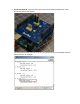
. First test, Strain1 : Connect a F/F jumper wire from the positive excitation pin to the adjacent pin (see picture below). You should read a value near the maximum (675) (values of [665, 675] are acceptable). See the picture below for an example. Since the excitation voltage may not always be at 3.3 V DC (may be a bit lower), the final output may be lower, too.
. Second test, Strain1 : Connect a F/F jumper wire from the positive excitation pin to the pin two over (see picture below). You should read a value near the minimum (~0) (values of [0,5] are acceptable). See the picture below for an example.
. Third test, Strain2 : Connect a F/F jumper wire from the positive excitation pin to the adjacent pin (see picture below). You should read a value near the maximum (675) (values of [665, 675] are acceptable). See the picture below for an example.
. Fourth test, Strain2 : Connect a F/F jumper wire from the positive excitation pin to the pin two over (see picture below). You should read a value near the minimum (~0) (values of [0,5] are acceptable). See the picture below for an example.
. If the board passes steps #5,6,7,8,9 then it is considering working. If the values are not very near the minimum and maximum during one of the tests, then the board should be considered defective.