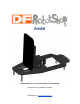
ROVER DFRobotShop Rover Cell Phone Expansion Plate Setup This guide is only available in English RobotShop Inc. www.RobotShop.
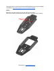
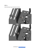
This guide assumes you have assembled the DFRobotShop Rover as per the default configuration: https://www.youtube.com/watch?v=MWWoEul9Qsk STEP 1 Break four connection points to free up the opening for the shield. This is done to allow for unobstructed access to make connections to the IO shield. RobotShop Inc. www.RobotShop.
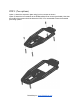
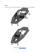
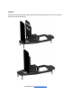
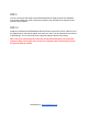
STEP 2 (Two options) Option 1) Attach the expansion plate using four 3mm screws as shown. Option 2) Attach the hex standoffs to the DFRobotShop Rover screws (preferable). Note that the heads of the screws should be below the PCB; if not, reassemble to have the threaded part facing upward. RobotShop Inc. www.RobotShop.
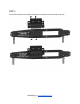
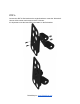
STEP 3 Connect the multipurpose bracket using two 256 machine screws and two 256 nuts. RobotShop Inc. www.RobotShop.
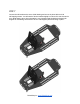
STEP 4 Add ball bearing using the ball bearing hardware RobotShop Inc. www.RobotShop.
STEP 5 Connect the servo to the multipurpose bracket using the servo mounting hardware provided. RobotShop Inc. www.RobotShop.
STEP 6 Connect the ARF01 flat bracket to the angled bracket to create the “tilt bracket”. Use two 256 countersunk screws and two 256 nuts. It is important to use the lower SES hole pattern on the flat bracket. RobotShop Inc. www.RobotShop.
STEP 7 Connect the tilt bracket to the servo & ball bearing and secure in place with two 256 selftapping screws. You will need to flex the bracket slightly in order to fit it over the servo’s horn. Note that the servo horn orientation is very important and should be horizontal (90 degrees is considering servo travel to be 0 to 180 degrees) before securing in place. RobotShop Inc. www.RobotShop.
STEP 8 Stick the antislip smart phone pad to the ARF01 bracket. This pad can be run under warm water if it becomes less sticky. RobotShop Inc. www.RobotShop.
STEP 9 You can now secure the setup to the DFRobotShop Rover using the 3mm Hex Standoffs. If the screws holding the motor in place are top down, they will need to be reversed so the thread is facing upward. STEP 10 Install the IO shield to the DFRobotShop Rover PCB and connect the servo’s cable to one of the digital IO pins, ensuring the yellow connection is to the ‘D’ pin and the black connection is to the GND pin. You can move the servo using the Arduino’s builtin servo library.