Mini RobotShop Rover Development Platform Mechanical Assembly Guide Revision 1.1 (Oct 2014) This manual is offered in English only. www.RobotShop.
Introduction Thank you for purchasing the Mini RobotShop Rover. Below you will find a step by step guide for assembling the gearbox and frame. Should you have purchased the Smartphone version of the kit, the guide also includes instructions on how to assemble the tilt mechanism and servo motor. Note that the frame has mounting holes for either an Arduino compatible board or the Raspberry Pi. Which holes are used for which board is explained at step 20.
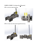
GEARBOX ASSEMBLY (Configuration A Required) STEP 1A (2x): Drive Gear Positioning STEP 1B: Center Axle Collar Positioning (With Set Screw)
STEP 2 (2x): Motor Pinion Note: At this point you can also attach / solder wires to the motor. We suggest the wires be at least 14cm long. There are five crimps included with the kit as well as 25” of 22 AWG wire. You can cut the wire into four equal sections, strip ~5mm of wire from each end and use the crimps between one end of the wire and the motor terminals. Alternatively, you can use your own materials.
STEP 3: Brass Bearings
STEP 4: Center Axle + Gear
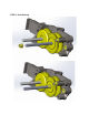
STEP 5: Plastic Gears (Righe Side)
STEP 6: Plastic Gears (Right Side)
STEP 7: Plastic Spacer + Brass Bearing
STEP 8: Brass Bearing
STEP 9: Right Drive Shaft + Brass Bearing
STEP 10: Center Bracket
STEP 11: Brass Bearings
STEP 12: Gears (Left Side)
STEP 13: Plastic Spacer + Brass Bearing
STEP 14: Shaft Collar (note: NO set screw) + Brass Bearing
STEP 15: Left Drive Shaft + Brass Bearing
STEP 16: Left Bracket
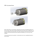
STEP 17: DC Motors
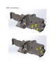
STEP 19: Spacers
The locations for the hex standoffs are determined based on the board you plan to connect. The Mini RobotShop Rover has mounting holes for either an Arduino (Uno for example) or a Raspberry Pi. The plate is symmetric. Arduino The Arduino mounting uses three (or four) hex standoffs, one of which is shared with the Tamiya Twin Motor Gear Box mounting (used instead of the 3mm screw and nut included with the Tamiya Twin Motor Gear Box). The USB connector / barrel connector face the rear of the board.
STEP 20: Standoffs for Electronics (Arduino shown)
STEP 21: Base Plate to Gear Box
STEP 22: Top Support Plate (Optional)
STEP 23: Supports
STEP 24A: Flex Side Panels Outward
STEP 24B: Slide Side Panels Over Front “Locks” Then Straighten
STEP 24C Push Bottom Support Plate Tab Below the Base; Slide Rear to Lock Note: The lower support plate has a tab at the top. This tab fits into the slot in the base and keeps all lexan parts in place without using screws.
STEP 25: Idler Sprockets
STEP 26: Drive Sprockets
STEP 27 (2x) Connect Only 1x Long + 1x Medium Track Length Per Side
STEP 28 (Optional) RobotShop 1000mAh, 3.7V LiPo Battery Note: Battery is 3cm wide x 0.55cm high x 5.6cm long If your battery is larger or does not fit, remove the top support plate and use the doublesided tape or your own method to secure your battery in place. There is foam provided to provide a tighter fit should your battery fit between the top support plate and frame.
STEP 29: Tracks
STEP 30: Microcontroller (Arduino Uno as example) A Microcontroller is not included with the basic chassis kit. Note that only three out of the four standoffs are used the fourth simply acts as support.
Cell Phone Mounting Certain versions of the Mini DFRobotShop Rover include mounting for a smartphone.
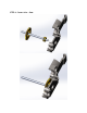
STEP 32: Connect Plastic Standoffs to SES to Arduino Lexan Plate Note that only three holes can be used with the DFRobotShop Rover Motor Shield
STEP 32: Connect Multipurpose Bracket to SES-Arduino Lexan Plate
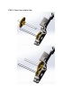
STEP 33: Attach the Bearing
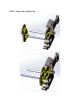
STEP 34: Mount the Servo
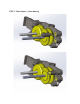
STEP 35: Position the Servo Horn The servo horn’s orientation is very important. If you moved the horn during assembly, you may need to recenter it via the software to ensure that when you send the servo the “neutral” (1500us) position, the cell phone bracket does not put pressure against the SESArduino Lexan plate. Connect the servo to the DFRobotShop Rover Shield (via an Analog pin) ensuring the black wire from the servo is connected to GND and the yellow wire connects to “S” (signal).
Motor Controller For an Arduino, we strongly suggest the DFRobotShop Rover Mobile Robot Shield. ● Standard Arduino Shield Format (with stacking headers) ● Dual motor controller (L298P) with two pairs of screw terminals for motor connections ● LiPo boost (to power the Arduino and shield using only one 3.7V LiPo battery via Vin) ● 3.