Installation, Use and Maintenance Manual GA Line ACF Series Gas fired absorption chiller Natural gas/LPG fired
Revision: M Code: D-LBR357 This Manual has been drawn up and printed by Robur S.p.A.; whole or partial reproduction of this manual is forbidden. The original is filed at Robur S.p.A. Any use of this manual other than for personal consultation must be previously authorised by Robur S.p.A. The rights of those who have legitimately filed the registered trademarks contained within this publication are not affected. With the aim of continuously improving the quality of its products, Robur S.p.A.
INDEX OF CONTENTS I INTRODUCTION �����������������������������������������������4 II SYMBOLS AND DEFINITIONS �������������������������4 II.1 Key to symbols ����������������������������������������������������������������������4 II.2 Terms and definitions ���������������������������������������������������������4 3.7 System water quality ������������������������������������������������������� 21 3.8 Water system filling ���������������������������������������������������������� 22 3.
I Introduction I INTRODUCTION Manual This Manual is an integral part of the GA unit and must be handed to the end user together with the appliance. Recipients This Manual is intended for: ▶▶ end user, for appropriate and safe use of the appliance; II II.1 ▶▶ qualified installer, for correct appliance installation; ▶▶ designer, for specific information on the appliance.
III ▶ ▶ efore performing any operation on gas ducting B components, close the gas cock. pon completing any procedure, perform the leak U test according to regulations in force. Warnings Electrical safety depends on effective earthing system, correctly connected to the appliance and installed according to the regulations in force.
1 Features and technical data Decommissioning and disposal If the appliance is to be disposed of, contact the manufacturer for its disposal. ▶▶ Electrical systems and equipment. ▶▶ Heating and air conditioning systems, and chillers. ▶▶ Fire safety and prevention. ▶▶ Any other applicable law, standard and regulation.
1 ▶▶ ▶▶ ▶▶ ▶▶ CF standard, for residential/retail/industrial cooling sysA tems with chilled water up to +3 °C. R with heat recovery exchanger, for residential/retail/inH dustrial cooling systems with chilled water up to +3 °C, plus recovery exchanger hot water up to +80 °C (e.g.
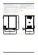
1 Features and technical data Figure 1.2 – GA-ACF silenced version dimensions Figure 1.
1 Figure 1.
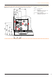
1 1.3 Features and technical data COMPONENTS Figure 1.5 – Internal components - front view LEGEND 1.Combustion air intake 2.Blower 3. Gas valve 4.Electrical Panel 5.Oil pump 6.Water inlet connection Ø 1"1/4 F 7.Water flow connection Ø 1"1/4 F 8.Gas connection 9.Ambient temperature probe 10.
1 Features and technical data Figure 1.6 – Left side internal components LEGEND 1.Ignition transformer 2.Flue gas thermostat 3.
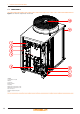
1 Features and technical data Figure 1.7 – Right side internal components LEGEND 1.Safety valve 2.Manual air vent 3.Inlet temperature probe 4.TG Probe 5.Limit thermostat 6.Flow temperature probe 7.Water flow switch 8.
1 1.4 Features and technical data ELECTRICAL WIRING DIAGRAM Figure 1.
1 Features and technical data Figure 1.9 – GA-ACF-HR Unit wiring diagram LEGEND TER 230Vac power supply terminal board SCH electronic board (S61) GV gas solenoid valve LS gas flow control lamp PSW air pressure switch THM outlet water temperature probe THR inlet water temperature probe TCN condenser output temperature probe TA ambient air temperature probe 1.
1 Features and technical data Figure 1.10 – Electronic board S61 LEGEND SCH S61" electronic board THMF water delivery temperature probe input THRF water return temperature probe input TCN condenser outlet temperature probe input TA ambient air temperature probe input TG generator temperature probe input (condenser input) TA1 not used TA2 not used SRT1 oil pump rotation sensor input SRT2 not used JP12 not used 1.
1 Features and technical data 1.6.2 Control system (2) with external request For connection of the selected device to the appliance's electronic board please refer to Paragraph 4.4 p. 25. The appliance may also be controlled via generic request devices (e.g. thermostats, clocks, buttons, contactors...) fitted with voltage-free NO contact. This system only provides elementary control (on/off, with fixed set-point temperature), thus without the important system functions (1).
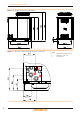
2 ACF60-00 TYPE thread width depth height silenced height In operation Gas fitting Size Weight "G mm mm mm mm kg ACF60-00 HR ACF60-00 TK Transport and placement ACF60-00 HT ACF60-00 LB F 3/4 850 1230 1290 1540 360 Note: 390 380 (6) ± 10% according to the power supply voltage and tolerance on electrical motors consumption (7) Sound power values detected in compliance with the intensity measurement methodology set forth by standard EN ISO 9614.
2 Transport and placement Figure 2.1 – Instruction for lifting In the event of handling with forklift or pallet truck, comply with the handling methods shown on the packing. 2.3 APPLIANCE POSITIONING ▶▶ ▶▶ Do not install inside a room The appliance is type-approved for external installation. ▶ ▶ ▶▶ o not install inside a room, not even if it has D openings. In no event start the appliance inside a room.
3 Plumbing installer Clearances around the appliance The minimum clearance distances shown in Figure 2.2 p. 19 (bar any stricter regulations) are required for safety, operation and maintenance. Figure 2.2 – Clearances (2) - installation on terrace or roof 2.5 MOUNTING BASE ▶▶ ▶▶ Mounting base constructive features ▶▶ Place the appliance on a levelled flat surface made of fireproof material and able to withstand its weight.
3 Plumbing installer a hydraulic separator, or possibly by a tank that also acts as inertial volume/thermal inertia. Constant water flow rate The GA unit works with constant, water flow and ON/OFF operative mode. System and components must be designed and installed consistently. Minimum water content ▶▶ ▶▶ F or each GA unit provide a minimum water content in the installation of at least 70 litres. I f necessary, provide for an inertial volume, to be suitably sized (see design manual).
3 ▶▶ 1 WATER CIRCULATION PUMP, towards the appliance; on the output water piping (m) ▶▶ 1 SAFETY VALVE (3 bar); ▶▶ 1 EXPANSION TANK of the individual unit. Figure 3.3 – Hydraulic plan LEGEND 1 Anti vibration joint 2 Pressure gauge 3 Flow rate adjustment valve 4 Water filter 5 Shut off valves 6 Water pump (primary circuit) 7 Safety valve (3 bar) 8 Expansion tank 9 Hydraulic separator / inertial tank with 4 fittings 10 Water pump (secondary circuit) 3.
3 Plumbing installer Adhere to the chemical-physical parameters in Table 3.2 p. 22 and the regulations on water treatment for residential and industrial heating systems. ▶ 3.8 WATER SYSTEM FILLING Table 3.2 – Chemical and physical parameters of water CHEMICAL AND PHYSICAL PARAMETERS OF WATER IN HEATING/COOLING SYSTEMS UNIT OF PARAMETER MEASUREMENT ALLOWABLE RANGE pH \ >7 (1) Chlorides mg/l < 125 (2) °f < 15 Total hardness (CaCO3) °d < 8.4 Iron mg/kg < 0.5 (3) Copper mg/kg < 0.
4 Electrical installer Gas supply pressure Product categories Countries of destination I3B/P I3B MT G20 [mbar] G25 [mbar] Non conforming gas pressure (Table 3.3 p. 22) may damage the appliance and be hazardous. Vertical pipes and condensate ▶▶ 4 Vertical gas pipes must be fitted with siphon and discharge of the condensate that may form inside the pipe. ▶▶ G30 [mbar] G31 [mbar] 30 30 30 G25.1 [mbar] G27 [mbar] G2,350 [mbar] If necessary, insulate the piping.
4 Electrical installer Figure 4.1 – GA-ACF Electrical Panel LEGEND A CAN-BUS cable gland B S61 electronic boards C ME and TER terminal boards D transformer 230/23 V AC E flame controller F circulation pump power supply and control cable gland G GA power supply cable gland Terminals: TER terminal box L-(PE)-N phase/earth/neutral GA power supply MA terminal box N-(PE)-L neutral/earth/phase circulation pump power supply 3-4 circulation pump enable 4.
4 4.4 ADJUSTMENT AND CONTROL ▶▶ ▶▶ Control systems, options (1) (2) Two separate control systems are provided, each with specific features, components and diagrams (Figures 4.4 p. 26, 4.5 p. 26): ▶▶ System (1), with DDC control (with CAN-BUS connection). ▶▶ System (2), with an external request.
4 Electrical installer Figure 4.4 – Connexion câble CAN BUS for plants with one unit LEGEND DDC direct digital control SCH electronic board S61 J1 Jumper CAN-BUS in board S61 J21 Jumper CAN-BUS in board DDC A terminal nodes connection - (3 wires; J1 e J21 = "closed") H,L,GND data signal wires (rif. cables table) External request Figure 4.5 – External request connection (System (2) see also Paragraph 1.6 p. 15) It is required to arrange: ▶▶ request device (e.g. thermostat, clock, button, ...
4 4.5 WATER CIRCULATION PUMP Electrical installer How to connect the CONSTANT FLOW circulating pump Constant flow circulating pump It must be mandatorily controlled from the S61 electronic board. The diagram in Figure 4.6 p. 27 is for pumps < 700 W. For pumps > 700 W it is required to add a control relay and arrange Jumper J10 OPEN. Access the Electrical Board of the appliance according to the Procedure 4.2 p. 23: 1. c onnect board S61, to terminals 3-4 of terminal board (MA); 2. Jumper J10 CLOSED.
5 First switch on Figure 4.7 – Recovery exchanger pump connection wiring diagram 5 FIRST SWITCH ON First Start-Up entails checking/setting up the combustion parameters and may exclusively be carried out by a Robur TAC. NEITHER the user NOR the installation technician is authorised to perform such operations, under penalty of voiding the warranty. 5.
6 6 Routine operation ROUTINE OPERATION This section is for the end user. 6.1 WARNINGS Although the external request is in the "ON" position, this does not mean the appliance will start immediately, but it will only start when there are actual service demands. General warnings Prior to using the appliance carefully read the warnings in Chapter III p. 4, providing important information on regulations and on safety.
6 Routine operation The appliance's electronic board (S61) Figure 6.1 LEGEND Controller S61 (in every unit) Electronic board S61 Display The 4-digit display of the S61 board (Detail A Figure 6.1 p. 30) is as follows: ▶▶ the first digit on the left, green) indicates the menu number (e.g. "0.", "1.", "2.", ... "8."); ▶▶ the last three digits (on the right, red) indicate a code or a value for a parameter, among those included in the selected menu (e.g. "__6" "_20", "161"). (e.g. menu+parameter "1.
6 2. R emove the cover of the electrical board to access the S61 board knob. 2. D isplay the parameter value by pressing the knob; the previously set value is displayed (from 3 to 25 °C); to reconfirm the pre-existing value press the knob again, otherwise go to point 3. 3. A ct on the knob by means of the special key through the suitable hole. 3. T urn the knob to modify the value, increasing or decreasing it, and press it to set the new value; 4.
7 Maintenance 4. E xit menu 2 and the menu list, by selecting and pressing letter "E" twice, and go back to the normal display of detected temperature data. 6.
8 SCHEDULED MAINTENANCE OPERATIONS Clean the electrodes of ignition and flame sensing Diagnostics TO BE PERFORMED AT LEAST ONE EVERY TWO YEARS √ √ √ √ √ Check that the condensate discharge is clean √ √ Replace the silicone gasket between the front plate and the exchanger √ √ *Only in case the analysis of combustion products is non-compliant 7.4 PERIODS OF INACTIVITY active antifreeze protection is missing, Paragraph 3.5 p. 21).
8 Diagnostics CODES DESCRIPTION Warning (u) 10 INSUFFICIENT WATER FLOW Reset is automatic when the triggering condition ceases. 11 INSUFFICIENT ROTATION OF OIL PRESSURE PUMP Reset occurs automatically 20 minutes after the code is generated. 12 FLAME CONTROL UNIT ARREST Reset is automatic up to 4 attempts (in about 5 minutes).
Appendices APPENDICES 1 DECLARATION OF CONFORMITY Figure 1 EC – DECLARATION OF CONFORMITY Manufacturer : Robur S.p.A. Address : Via Parigi 4/6 City, Country : Verdellino/Zingonia 24040 (Bg), Italy This is to declare that the ROBUR Gas Absortion Heat Pump (GAHP) are in conformity with the following ECDirectives: 2006/42/EC Machinery Directive with subsequent amendments and integrations. 2004/108/EC Electromagnetic Compatibility with subsequent amendments and integrations.
12/01/2015 15MCMSDC001 Revision: M Robur is dedicated to dynamic progression in research, development and promotion of safe, environmentally-friendly, energy-efficiency products, through the commitment and caring of its employees and partners. Code: D-LBR357 Robur mission Robur Spa advanced climate control technologies Via Parigi 4/6 24040 Verdellino/Zingonia (Bg) Italy T +39 035 888111⇒F +39 035 884165 www.robur.it robur@robur.