Installation, user and maintenance manual GAHP-A air-water gas absorption heat pump PRO platform powered by gas and renewable energy
Revision: B Code: D-LBR548 This manual has been drawn up and printed by Robur S.p.A.; whole or partial reproduction of this manual is prohibited. The original is filed at Robur S.p.A. Any use of this manual other than for personal consultation must be previously authorised by Robur S.p.A. The rights of those who have legitimately filed the registered trademarks contained within this publication are not affected. With the aim of continuously improving the quality of its products, Robur S.p.A.
Installation, user and maintenance manual – GAHP-A Index of contents 1 PREFACE ������������������������������������������������������������������������������������������������������������5 2 OVERVIEW AND TECHNICAL CHARACTERISTICS �����������������������������������������7 2.1 WARNINGS ��������������������������������������������������������������������������������������������������������������������������������������������������������������������������������������� 7 2.
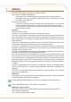
Installation, user and maintenance manual – GAHP-A 1 PREFACE This Installation, user and maintenance manual is a guide to the installation and operation of the Air-Water gas absorption heat pump "GAHP-A". This manual is specifically intended for: • final users for the use of the appliance according to their own requirements; • Installation technicians (hydraulic and electrical) for the carrying out of a correct installation of the appliance.
DDC: digital control panel (Direct Digital Controller). TAC: Technical Assistance Centre (authorised by Robur S.p.A.).
Installation, user and maintenance manual – GAHP-A 2 OVERVIEW AND TECHNICAL CHARACTERISTICS In this section, for all users, you will find general warnings, the operating principle of the appliance and its manufacturing characteristics. This section also contains technical data and dimensional drawings of the appliance. 2.1 WARNINGS This manual constitutes an integral and essential part of the product and must be delivered to the user together with the appliance.
• r equest the assistance of professionally qualified personnel from a telephone far from the appliance. The appliance has a sealed circuit that may be classified as a pressurised container, i.e. with internal pressure higher than atmospheric pressure. The fluids contained in its sealed circuits are harmful if swallowed or inhaled, or if they come into contact with the skin. Do not carry out any operation on the sealed circuits of the appliance or on the valves present.
Installation, user and maintenance manual – GAHP-A • • • • • t he electricity and gas mains specifications correspond to the specifications on the nameplate; the mains gas pressure falls within the range of values specified in Table 6.
• eactivate the appliance immediately (if permitted and if no condition of danger d exists) by starting the shutdown cycle via the CCP (or DDC or consent switch) and waiting for it to terminate (approximately 7 minutes); • disconnect the appliance from the gas and electricity mains, cutting off gas supply by means of the appropriate valve and the power supply by means of the external circuit breaker provided by the electrical system installation technician on the appropriate panel.
Installation, user and maintenance manual – GAHP-A 2.3 TECHNICAL MANUFACTURING CHARACTERISTICS The appliance is supplied with the following technical manufacturing characteristics, control and safety components: • Steel sealed circuit, treated on the outside with epoxy paint. • Sealed combustion chamber suited for type C installation. • Metal mesh irradiation burner equipped with ignition and flame detection managed by an electronic control unit. • Tube coil heat recovery (AISI 304L ).
GAHP-A LT gas consumption methane G20 (nominal) G30 (nominal) G31 (nominal) GAHP-A LT S m3/h kg/h kg/h 2,72 (3) 2,03 (4) 2,00 (4) V 230 SINGLE PHASE ELECTRICAL SPECIFICATIONS Voltage TYPE Power supply Frequency Electrical power absorption Degree of protection INSTALLATION DATA Level of acoustic pressure at 10 meters (maximum) Minimum storage temperature Maximum operating pressure Water content inside the apparatus nominal IP Gas fitting Fume outlet Maximum condensation water flow rate Size Weight
Installation, user and maintenance manual – GAHP-A GAHP-A HT Hot water delivery temperature Hot water return temperature Hot water flow rate Hot water pressure drop Ambient air temperature (dry bulb) Thermal differential gas consumption maximum for heating maximum for ACS maximum heating maximum for ACS minimum nominal maximum minimum nominal water pressure (A7W50) maximum minimum nominal methane G20 (nominal) G30 (nominal) G31 (nominal) GAHP-A HT S °C °C °C °C °C l/h l/h l/h 65 70 55 60 2 3000 4000 10
Table 2.3 – PED data GAHP-A LT GAHP-A HT GAHP-A LT S PED data COMPONENTS UNDER PRESSURE Generator Leveling chamber Evaporator Cooling volume transformer Cooling absorber solution Solution pump TEST PRESSURE (IN AIR) SAFETY VALVE PRESSURE CALIBRATION FILLING RATIO l l l l l l bar g bar g kg of NH3/l FLUID GROUP 2.5 DIMENSIONS AND SERVICE PANEL Figure 2.1 – Size (Standard ventilation) Front and side views (dimensions in mm).
Installation, user and maintenance manual – GAHP-A Figure 2.2 – Size Front and side views (dimensions in mm). Figure 2.
Installation, user and maintenance manual – GAHP-A 3 NORMAL OPERATION In this section you will find all the indications necessary for the activation, regulation and control of operation of the appliance depending on the type of installation and control setup. • TYPE A (NOT APPLICABLE at PRO Platform): controlled by Comfort Control Panel. • TYPE B: controlled by DDC (see Figure 5.3 Direct Digital Control (DDC) → 41). • TYPE C: controlled by consent switch (e.g.
Shutting off the power supply while the appliance is running can irreparably damage its internal components! Start up Switch on the appliance by means of the on/off command (placing it in the "ON" position). When activation is successful, the appliance is managed by the S61 controller in its electrical panel (see paragraph 3.2 ON-BOARD ELECTRONICS → 19). The controller’s display may be viewed through the viewing hole on the front panel of the unit itself.
Installation, user and maintenance manual – GAHP-A For the operating codes generated by the CCP/DDC, refer to the manuals supplied with the unit. 3.2 ON-BOARD ELECTRONICS The following descriptions refer to the S61 controller with firmware version 3.015. The appliance is fitted with an S61 microprocessor controller with Mod10 combustion modulation controller mounted above it (see Figure 3.1 On-board controller → 19).
MENU Menu 5 Menu 6 Menu 7 Menu 8 E MENU DESCRIPTION TECHNICAL ASSISTANCE CENTRE SETTINGS TECHNICAL ASSISTANCE CENTRE SETTINGS (MACHINE TYPE) VIEW DIGITAL IMPUTS (MENU NOT USED) (EXIT MENU) THE DISPLAY SHOWS 5. 6. 7. 8. E. Menu list of electronic board Menus 0, 1 and 7 are Viewing Menus: they only allow the information displayed to be read, and not modified.
Installation, user and maintenance manual – GAHP-A You will need: the appliance's electrical power switches set to "ON"; the controller's display sequentially shows the operating data (temperature, delta T) regarding the current mode (e.g.: heating) and any active operating codes ("u/E..."). 1. R emove the front panel by removing the fixing screws. 2. Remove the cover of the electrical panel to access the knob. 3.
Table 3.3 – Menu 2 ACTION 20 21 22 23 24 25 E REQUIRED FOR EXECUTION Reset flame controller arrest Reset other operating codes Manual defrost Timed forcing to minimum power Timed forcing to maximum power Regulation of power (EXIT MENU) SHOWN ON DISPLAY AS 2. 20 2. 21 2. 22 2. 23 2. 24 2. 25 2. E The general operating codes of the controller can be reset with functions "20" and "21".
Installation, user and maintenance manual – GAHP-A Manual defrosting; the execution of the manual defrosting command, provided that the conditions exist (these are verified electronically), allows the fan coil to be defrosted, overriding software control regarding the timing of this operation. Defrosting mode is managed automatically by the on-board electronics and is activated only under specific operating conditions (the on-board electronics verify the appropriate requirements).
2. D isconnect the appliance from the power supply, putting the external disconnection switch in the OFF position (see GS in Figure 5.5 Electrical wiring diagram → 43) provided in the appropriate panel by the installation technician. 3. Close the gas valve. Do not leave the appliance connected to power and gas supply if it is expected to remain inactive for a long period. If you wish to disconnect the appliance during the winter, one of the following three conditions must be met: 1.
Installation, user and maintenance manual – GAHP-A 5. c heck that the condensate siphon is NOT empty or blocked (see Paragraph 4.5 CONDENSATE DISCHARGE CONNECTION → 32); 6. check that the air/fumes pipes are not blocked. 7. switch on the appliance by means of the on/off command (or DDC if present and in control mode, or via CCP, if present).
Installation, user and maintenance manual – GAHP-A 4 HYDRAULIC SYSTEM INSTALLATION TECHNICIAN In this section you will find all the instructions necessary for installing the appliance from a hydraulic viewpoint. Before proceeding with operations to create the hydraulic and gas supply plant of the appliance, the professionally qualified personnel concerned are advised to read Paragraph 2.1 WARNINGS → 7: it provides important information regarding installation safety and references to current regulations.
If the appliance has to be lifted, connect braces to the openings provided on the base bar, and use suspension and spacer bars to prevent these braces from damaging the panels during moving operations (see Figure 4.1 Instruction for lifting → 28). The lifting crane and all accessory devices (braces, cables, bars) must be suitable sized for the load to be lifted. For the weight of the appliance, consult Table 2.1 GAHP-A LT technical data → 11 or Table 2.2 GAHP-A HT technical data → 12.
Installation, user and maintenance manual – GAHP-A controlled” spread of water around the appliance and the consequent risk that a layer of ice will form (with the danger of falls on the part of passing people). The manufacturer may not be held responsible for any damage arising from the failure to observe this warning.
Figure 4.2 – Clearances Position the appliance preferably out of range of rooms and/or environments where strict silence is required, such as bedrooms, meeting rooms, etc. Evaluate the acoustic impact of the appliance on the basis of the installation site: avoid locating the appliance in positions (corners of buildings, etc.) that could amplify the noise it produces (reverb effect). 4.
Installation, user and maintenance manual – GAHP-A WARNING: the presence of free chlorine (CL2) in the water can damage steel or copper parts of the installation. Make sure that water does not contain free chlorine; if in doubt, it is recommended to make a specific analysis and/or add to water some specific product (by example, Alphi-11 Protector, by Fernox, which also has inhibitory effect against possible icing). For further details, please contact directly Robur SpA (phone: 035 888 111).
For the others components to instal on the system refer to "Design Manual" for the GAHP line. For further information or technical support in this regard, contact Robur S.p.A.'s Presales Office (tel.+39 035.888.111) or visite site www.robur.it. The operations necessary for the First Activation or Regulation of the appliance must be carried out exclusively by an authorised Robur Technical Assistance Centre (TAC). These operations are described in Section 6 INITIAL ACTIVATION AND MAINTENANCE → 59.
Installation, user and maintenance manual – GAHP-A Figure 4.3 – Position of condensate discharge and manual reset fumes thermostat LEGEND A Condensate drain pipe B Condensate drain siphon C Manual reset fumes thermostat The condensate discharge to the sewer must be: • sized so as to discharge the maximum condensation flow (see Table 2.1 GAHP-A LT technical data → 11 or Table 2.
4.6 FILLING OF HYDRAULIC CIRCUIT After having completed all the connections of the hydraulic, electrical and gas supply plants, the hydraulic system installation technician can proceed with filling the hydraulic circuit, observing the following stages: You will need: the appliance connected hydraulically and electrically. 1. A ctivate the automatic air bleeding valves present in the plant and open all thermostatic valves. 2.
Installation, user and maintenance manual – GAHP-A This Table 4.2 Percentage of monoethylene glycol → 35 should be taken into account for the sizing of the pipes and the circulation pump (for calculation of internal pressure drops of the appliance, refer to the Table 2.1 GAHP-A LT technical data → 11 or Table 2.2 GAHP-A HT technical data → 12). Nevertheless, it is advisable to consult the technical specifications of the monoethylene glycol used.
Figure 4.4 – Fume outlet LEGEND A Curve 90° Ø 80 B Pipe Ø 80 Lg.300 mm w/terminal C rain cover 4.8 PROGRAMMING OF HYDRAULIC PARAMETERS The operations described in this paragraph are necessary only if the appliance is not connected to a DDC or to a CCP. If the appliance is connected to a DDC, follow the instructions given in the DDC manuals exclusively. This paragraph explains how to set the hydraulic parameters on the electronic board of the appliance.
Installation, user and maintenance manual – GAHP-A • ater set-point, parameter 161: this parameter sets the water temperature that, W when reached, causes the appliance to be deactivated (when the power modulation is not active - parameter 181) • Water differential, parameter 162: this parameter represents an interval in degrees that, when added to the set-point, defines the temperature at which the appliance is reactivated.
Installation, user and maintenance manual – GAHP-A 5 ELECTRICAL SYSTEM INSTALLATION TECHNICIAN This section illustrates the operations to perform for the correct electrical installation of the appliance, and contains electrical diagrams that may be of use in the event of maintenance operations. Installation of the appliance may only be carried out by firms that are qualified in accordance with current legislation in the country of installation, i.e. by professionally qualified personnel.
Table 5.1 – Electronic board S61 CODE SCH1 SCH3 A1, A2 ENC F1 F2 F3 F4 FAN (BK, WH, BR) FL FS5 (24V AC) IGN.BOX (L, N) J1 J10 J82 JP10 JP12 JTAG MAIN 230V (L, N) N.O. contact P7 (R, W, Y, o) P8 (GND, L, H) PUMP 230V (L, N) SPI SRT1 SRT2 TA TA1 TA2 TCN TF TG THMF THRF TL SCH S61 40 DESCRIPTION Electronic board S61 Mod10 electronic controller (see figure for further details) Auxiliary inputs Knob Fuse T 2A Fuse F 10A Fuse T 2A Fuse T 3.
Installation, user and maintenance manual – GAHP-A Figure 5.2 – Mod10 controller LEGEND HFLOW Not used CFLOW Not used J51 SPI connector HPMP Primary circuit hot water pump control output (0-10 V) [E3 A/GS/WS] CPMP Cold side water pump control output [E3 GS/WS] NC1-C1 Status indication of locking warnig/error CN5 Blower control J82 W10 auxiliary controller connector J83 W10 cable shielding connection W10 CN1 Inputs 0-10V (not used) Mod10 controller Figure 5.
LEGEND SCH1 S61 controller SCH2 W10 controller SCH3 Mod10 controller TER Power terminal block CNTBOX Flame controller PWRTR Controller transformer BLW Blower PMP Hydraulic pump IGNTR Ignition transformer IGN Ignition electrodes FLS Flame sensor LS Gas valve ON indicator lamp GV Gas solenoid valve TC Manual fumes thermostat TL Generator limit thermostat FM Flowmeter (only for E3-A) FL Flowmeter (only for GAHP-A) CWS Condensation water sensor VD Defrosting valve TM Thermostat for electrom
Installation, user and maintenance manual – GAHP-A 5.2 HOW TO CONNECT THE APPLIANCE ELECTRICALLY Before making the electrical connections, make sure that work is not carried out on live elements. You will need: the appliance in its permanent location. 1. P repare a cable of the FG7(O)R 3Gx1.5 type for the power supply to the appliance. 2.
• T erminal nodes are appliances or DDCs that are connected to one other element only. • Intermediate nodes are appliances or DDCs that are connected to two other elements. The diagram in Figure 5.6 Example of CAN BUS → 44 gives an example of a CAN BUS network: 3 appliances are connected to each other and to 1 DDC. Appliance D and the DDC (A) are terminal nodes, while appliances C and B are intermediate nodes as they are connected to 2 elements.
Installation, user and maintenance manual – GAHP-A As shown in Table 5.2 CAN BUS cables type → 44, the CAN connection requires a CAN bus cable with 3 wires. If the available cable has more than 3 coloured wires, use the wires with the colours indicated in 5.2 CAN BUS cables type → 44 and cut the remaining ones. The ROBUR NETBUS cable is available as an accessory, see Section 7 ACCESSORIES → 67.
7. F ix the CAN bus cable (or two cables, according to the type of node being connected) to the cable fixing bracket in the upper part of the inside of the electrical panel so that the rolled-back sheathing makes solid contact with the metal bracket. The cables must be held firmly in place by the bracket if pulled. To position the jumpers on the board according to the type of node being configured: • If the appliance is a terminal node on the network (i.e.
Installation, user and maintenance manual – GAHP-A 1. D epending on the type of node being configured, set the DDC's jumpers J21 as shown in detail "A" or detail "B" in Figure 5.10 detail wires and jumpers J21 - terminal/intermediate node DDC → 48. If necessary, open the DDC's back panel (4 screws); after jumpers J21 have been correctly positioned, close the cover again and retighten the 4 screws. • If the DDC is an intermediate node on the network (with no.
Figure 5.9 – Connection from CAN BUS to connector P8 LEGEND A Insulating tape to protect board/shield B CAN BUS cable wires C CAN bus cable shield D terminal and screw for fixing Connection detail of cable CAN BUS. Figure 5.
Installation, user and maintenance manual – GAHP-A You will need: the appliance disconnected from the electricity supply 1. R emove the DDC's back panel by undoing the 4 bolts securing it. 2. Cut a suitable length of power cord (minimum 2x0.75 mm2). 3. Pass the power cord (DDC side) through the hole in the DDC's cover and hook up as shown in the example, with the following polarities: terminal 1 = 24 V; terminal 2 = 0 V; terminal 3 = ground.
Figure 5.12 – Connexion câble CAN BUS for plants with one unit LEGEND DDC direct digital control SCH electronic board S61 J1 Jumper CAN-BUS in board S61 J21 Jumper CAN-BUS in board DDC A terminal nodes connection - (3 wires; J1 e J21 = "closed") H,L,GND data signal wires (rif.
Installation, user and maintenance manual – GAHP-A LEGEND DDC direct digital control SCH electronic board S61 J1 Jumper CAN-BUS in board S61 J21 Jumper CAN-BUS in board DDC A terminal nodes connection - (3 wires; J1 e J21 = "closed") B intermediate node connection - (6 wires; J1="closed") H,L,Gnd data signal wires (rif. cables table) Figure 5.
Controlling the pump from the appliance's controller Control of the plant water circulation pump from the appliance's controller depends on the power rating of the pump itself. 2 cases may be distinguished: • Direct control from the controller with power absorbed by the pump less than 700 W. If the power absorbed by the pump is less than 700 W, make the connection as shown in Figure 5.
Installation, user and maintenance manual – GAHP-A Figure 5.15 – Electrical wiring diagram LEGEND SCH electronic board TER terminal board J10 jumper open N.O.
LEGEND SCH electronic board J10 jumper open N.O. CONTACT clean exit normally open L phase N neutral Components NOT SUPPLIED PMP water pump KP control pump relay GS general switch PTR safety transformer SELV IP bipolar pump switch Figure 5.
Installation, user and maintenance manual – GAHP-A the opening of the appliance's consent switch contacts, the circulation pump will thus continue to circulate the water in the plant for a further 10 minutes, thereby ensuring the complete dispersal of the heating energy produced. When the pump is controlled by the appliance's controller, this delay is automatically applied by the board. 5.4 TYPE C (Consent switch) In this type of installation and control, the system pump does not vary the flow rate.
How to connect the plant water circulation pump For how to connect the system pumps, see the section with this title in Paragraph 5.3 TYPE B (DDC) → 43. 5.5 HOW TO REMOTELY CONTROL THE FLAME CONTROLLER RESET The flame controller reset can be controlled remotely by installing a button (not supplied) to the flame controller inside the unit’s electrical panel. Connect the button as instructed below. You will need: the appliance disconnected from the electricity supply 1.
LEGEND 1 White 2 Grey 3 Orange 4 Green 5 Yellow/Black 6 Black 7 Yellow/Green (Ground) 8 Brown 9 Blue 10 Red 11 Violette 12 Pink PLS Reset button A Blind terminals Installation, user and maintenance manual – GAHP-A Figure 5.
Installation, user and maintenance manual – GAHP-A 6 INITIAL ACTIVATION AND MAINTENANCE In this section you will find the following information: • Indications required by the authorized Robur Technical Assistance Centre (TAC) in order to carry out the entire procedure of first start-up of the appliance. • Indications regarding maintenance operations of the appliance. At the end of the section you will find instructions for changing the type of gas.
In this case, the Robur TAC technician must: • Advise the user/installation technician of any installation anomaly. • Inform the user/installation technician of any situation that is deemed to be hazardous for the appliance and for people. • Inform of any missing documentation relative to the plant.
Installation, user and maintenance manual – GAHP-A During the first start-up procedure it is in any case necessary to: • check the dynamic gas mains pressure • check and adjust the appliance’s combustion parameters You will need: the appliance connected to the gas and electricity supply: switched off and with the gas cock closed; front panel removed. Check the dynamic gas mains pressure 1. Connect the manometer to the gas intake (see detail D, Figure 6.1 Gas valve → 61). 2.
E3-GS; E3-WS; E3-A; GAHP-GS; GAHP-WS; GAHP-A Product categories Countries of destination II2ELL3B/P DE II2Esi3P FR II2HS3B/P HU II2E3P LU II2L3B/P NL II2E3B/P II2ELwLs3B/P PL II2ELwLs3P I2E(R)B ; I3P BE I3P IS I2H LV I3B/P MT I3B G20 [mbar] 20 20 25 20 G25 [mbar] 20 25 25 20 20 20 20 25 Gas supply pressure G30 [mbar] G31 [mbar] G25.1 [mbar] 50 50 37 30 30 25 50 50 50 37 37 37 37 37 37 30 G27 [mbar] G2,350 [mbar] 20 20 13 13 20 30 30 30 If the pressure reading is not in line with Table 6.
Installation, user and maintenance manual – GAHP-A 7. W ith the appliance running, access menu 2 parameter 24 of the unit's controller: the display will flash "P_H1", press to confirm forcing maximum thermal power . 8. Check that, also following a regulation intervention on screw C, the value of CO2 corresponds to the value read in Table 6.2 Gas nozzles and content of CO2 → 65 at the "Content of CO2 with/Max modulation" line with tolerance of +0.2 -0.4.
• E lectrodes: check and repair in case of incorrect physical configuration, alumina deposits or degraded protective ceramic and gaskets. • Fumes limit thermostat and combustion unit: replace only after having identified the cause of the problem and made sure that it is not due to the heat exchanger overheating. If you replace it, track the new component. Extraordinary maintenance The operations described in this paragraph must be carried out as and when necessary.
Installation, user and maintenance manual – GAHP-A 14. c omplete the change of gas type by checking that all gas connections are sealed, including those not directly affected by this operation (using soapy water or another suitable method). 15. Now check and adjust the combustion parameters as indicated in the respective paragraph. Figure 6.
Installation, user and maintenance manual – GAHP-A 7 ACCESSORIES This section contains a list of the accessories that are available for the installation and use of the appliance. To order these accessories, contact Robur S.p.A. on +39 035.888111. Table 7.1 – Accessories ACCESSORIES Name Description Code CIRCULATION PUMPS Wilo-Stratos Para 25-11.
Installation, user and maintenance manual – GAHP-A 8 APPENDIX 8.1 MACHINE OPERATING CODES Table 8.1 – TABLE OF OPERATING CODES generated by S61 controller (firmware version 3.015) CODES E 401 DESCRIPTION FAULT ON RESET CIRCUIT OF FLAME CONTROL UNIT GENERATOR LIMIT TEMPERATURE THERMOSTAT GENERATOR LIMIT TEMPERATURE THERMOSTAT u 402 FUMES THERMOSTAT High temperature detected by limit thermostat on body of generator U 1 code active for 1 hour, or U 1 code generated 3 times in 2 hours of operation.
CODES DESCRIPTION TRIP CONDITIONS E 444 EVAPORATOR TEMPERATURE SENSOR FAULT Evaporator temperature probe fault u 446 HOT INLET WATER TEMPERATURE TOO HIGH u 447 LOW HOT WATER TEMPERATURE E 447 LOW HOT WATER TEMPERATURE Hot inlet water temperature higher than upper operating limit of the appliance (if the appliance is in operation). Hot water temperature lower than lower operating limit of the appliance (if the appliance is in operation).
Installation, user and maintenance manual – GAHP-A 79
La Mission Robur Robur Spa tecnologie avanzate per la climatizzazione Via Parigi 4/6 24040 Verdellino/Zingonia (Bg) Italy T +39 035 888111 F +39 035 884165 www.robur.it robur@robur.it Revision: B Code: D-LBR548 09 MCM SDC 006 15/07/2009 Robur is dedicated to dynamic progression in research, development and promotion of safe, environmentally-friendly, energy-efficiency products, through the commitment and caring of its employees and partners.