
Technical data


Installation, user and maintenance manual – GAHP-A
21
You will need: the appliance's electrical power switches set to "ON"; the controller's dis-
play sequentially shows the operating data (temperature, delta T) regarding the current
mode (e.g.: heating) and any active operating codes ("u/E...").
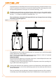
Remove the front panel by removing the xing screws.1.
Remove the cover of the electrical panel to access the knob.2.
Use the special key through the hole to operate the knob and access the control-3.
ler’s menus and parameters.
To display the menus just press the knob once: the display shows the rst menu: 4.
"0." (= menu 0).
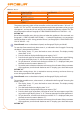
The display shows “0.”. To display the other menus, turn the knob clockwise; The 5.
display will read, in order: "1.", "2.", "3.", "4.", "5.", "6.", "7.", "8." and "E" (see Table 3.1
Menu of electronic board → 19).
To display the parameters in a given menu (for example, menu 0), turn the knob 6.
until it displays the menu in question (in the example: "0.") and press the knob: the
display will show the rst of the menu’s parameters, in this example "0.0" or "0.40"
(= menu 0, parameter "0" or "40").
In the same way: 7. turn the knob to scroll through content (menus, parameters, ac-
tions), press the knob to select/conrm the content (access a menu, display/set
a parameter, execute an action, quit or return to the previous level). For example,
to quit the menus, turn the knob to scroll through menus "0.", "1.", "2." etc. until the
controller displays the quit screen "E"; now press the knob to quit.
In the case of menus 0 and 1, the user can view any parameter. For information about
menu 2, refer to Paragraph 3.3 RESET OPERATIONS AND MANUAL DEFROSTING → 21. To
set the parameters of me nu 3, refer to Paragraph 4.8 PROGRAMMING OF HYDRAULIC PA-
RAMETERS → 36. The other menus are not for the User: the information in these menus is
dealt with in the sections dedicated to the installation technician or Robur TAC.
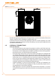
The special key allows the knob of the electronic board to be operated without opening
the cover of the electrical panel, so that operators are protected from live components.
When the necessary settings have been completed, put away the special key, replace the
cap on the aperture of the electrical panel and ret the front panel of the appliance.
3.3 RESET OPERATIONS AND MANUAL DEFROSTING
There are several possible reasons why the appliance may have error status and therefore
its operation arrested; such an error situation does not necessarily correspond to damage
or malfunction on the part of the appliance. The cause that has generated the error may
be temporary: for example, presence of air in the gas supply line or temporary power
failure.
The appliance can be reset with controller menu 2, the Comfort Control Panel (if present)
or the DDC (if present). In these two latter cases, refer to their documentation.
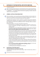
Reset appliance controller
The Table 3.3 Menu 2 → 22 shows the actions available in menu 2.
For regulatory reasons, the ame controller reset is in a dedicated voice of menu.