
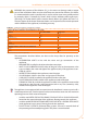
Technical data


32
For the others components to instal on the system refer to "Design Manual" for the GAHP
line. For further information or technical support in this regard, contact Robur S.p.A.'s
Presales Oce (tel.+39 035.888.111) or visite site www.robur.it.
The operations necessary for the First Activation or Regulation of the appliance must be
carried out exclusively by an authorised Robur Technical Assistance Centre (TAC). These
operations are described in Section 6 INITIAL ACTIVATION AND MAINTENANCE → 59.
The products' guarantee is void if initial activation is not carried out by a Robur TAC.
4.4 GAS SUPPLY SYSTEM
The installation of gas supply pipes must be carried out in compliance with norms and
other current regulations.
The gas mains pressure must be in the range given in Table 6.1 Network gas
pressure → 61.
Supplying gas to the appliance at higher pressures than those indicated above can dam-
age the gas valve, giving rise to a situation of danger.
For LPG systems t a rst stage pressure reducer of the ow necessary near the liquid gas
tank to reduce the pressure to 1.5 bar and a second stage pressure reducer from 1.5 to
0.03 bar near the appliance.
LPG may cause corrosion. The connectors between the pipes must be made of a material
that is resistant to this corrosive action.
Vertical gas pipes must be equipped with a siphon and provided with a drain for the con-
densate that may form inside the pipe during cold periods. It may also be necessary to
insulate the gas pipe to prevent the formation of excessive condensate.
In any case, provide a cut-o valve (cock) on the gas supply line, to isolate the appliance
if required.
For data regarding hourly fuel consumption of the appliance, refer to Table 2.1 GAHP-A LT
technical data → 11 or Table 2.2 GAHP-A HT technical data → 12.
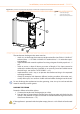
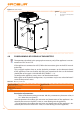
4.5 CONDENSATE DISCHARGE CONNECTION
The fumes condensate outlet is on the left of the unit.
The unit is supplied complete with a siphon to which a piece of pipe is attached. During
transport, the pipe is stored inside the unit’s left mounting bracket at the front of the
appliance.
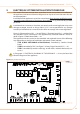
To install/connect the pipe, proceed as follows:
Pass the pipe through the hole in the left mounting bracket (see Figure 4.3 Position 1.
of condensate discharge and manual reset fumes thermostat → 33).
Connect the tube to a plastic condensate discharge manifold of the correct 2.
length.
The connection between the pipe and the condensate manifold must be in a vis-3.
ible location.