
Technical data

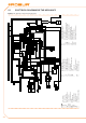


Installation, user and maintenance manual – GAHP-A
47
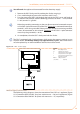
Depending on the type of node being congured, set the DDC's jumpers J21 as 1.
shown in detail "A" or detail "B" in Figure 5.10 detail wires and jumpers J21 - ter-
minal/intermediate node DDC → 48. If necessary, open the DDC's back pa nel (4
screws); after jumpers J21 have been correctly positioned, close the cover again
and retighten the 4 screws.
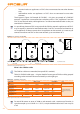
If the DDC is an • intermediate node on the network (with no. 6 wires in the orange
connector "P8"): set the jumpers "J21" as shown in detail "B" of Figure 5.10 detail
wires and jumpers J21 - terminal/intermediate node DDC → 48: Jumpers OPEN.
If the DDC is an • terminal node on the network (with no. 3 wires in the orange con-
nector "P8"): set the jumpers "J21" as shown in detail "A" of Figure 5.10 detail wires
and jumpers J21 - terminal/intermediate node DDC → 48: Jumpers CLOSED.
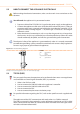
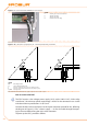
Prepare the orange CAN bus connector, from the supplied sleeve.2.
Cut a length of cable, long enough to allow it to be installed without kinking.3.
Remove the sheath for a length of approximately 70-80 mm, taking care not to cut 4.
the shielding (metallic shield and/or aluminium sheet and, if present, the bare con-
nector in contact with the shield) and wires contained inside.
Roll the shielding and connect it to a 4-mm eyelet terminal, as illustrated in Figure 5.
5.9 Connection from CAN BUS to connector P8 → 48, details C and D. Now proceed
as follows:
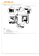
If the DDC is an 6. terminal node connect the three coloured wires to the orange
connector "P8", following the diagram provided in detail "A" of Figure 5.10 detail
wires and jumpers J21 - terminal/intermediate node DDC → 48. Observe the termi-
nal markings L, H, GND (on the DDC at the base of the socket "P8") which are given
both in Table 5.2 CAN BUS cables type → 44 and in the example.
If the DDC is an 7. intermediate node repeat the operations from step 2 to step 4 for
the other length of CAN bus cable required. Connect the six coloured wires to the
orange connector "P8", following the diagram provided in detail "B" of Figure 5.10
detail wires and jumpers J21 - terminal/intermediate node DDC → 48. Observe the
terminal markings L, H, GND (on the DDC at the base of the socket "P8") which are
given both in Table 5.2 CAN BUS cables type → 44 and in the example.
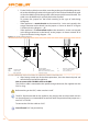
Insert the orange connector ("P8") with the wires rst into the opening prepared in 8.
the cover of the DDC, and then into the appropriate socket on the DDC itself, mak-
ing sure it is correctly inserted.
Use the rear cover bolts located near the CAN BUS socket to secure the 4 mm eyelet 9.
(or 2 eyelets) (detail D, Figure 5.9 Connection from CAN BUS to connector P8 → 48).
The cable should be secured against pulling out.