Robustel GoRugged M1000 Pro Serial to GPRS/EDGE Gateway For GSM/GPRS/EDGE Networks User Guide Document Name: Firmware: ModemConfigurator Pro: Date: Status: DocID: User Guide 1.0.1 1.0.2 2011‐12‐27 /Confidential /RT_M1000_Pro_v01.01 www.robustel.
Robustel GoRugged M1000 Pro User Guide About This Document This document describes the hardware and software of the Robustel M1000 Pro Serial to GPRS/EDGE Gateway. Copyright© Guangzhou Robustel Technologies Co., Limited All Rights Reserved. Trademarks and Permissions Robustel are trademark of Guangzhou Robustel Technologies Co. Limited. All other trademarks and trade names mentioned in this document are the property of their respective holders.
Robustel GoRugged M1000 Pro User Guide Important Notice Due to the nature of wireless communications, transmission and reception of data can never be guaranteed. Data may be delayed, corrupted (i.e., have errors) or be totally lost.
Robustel GoRugged M1000 Pro User Guide Do not drop, hit or shake the modem. Do not use the modem under extreme vibrating conditions. Do not pull the antenna or power supply cable. Attach/detach by holding the connector. Connect the modem only according to the instruction manual. Failure to do it will void the warranty. In case of problem, please contact authorized distributor. RT_M1000 Pro_UG_v01.01 Confidential 27.12.
Robustel GoRugged M1000 Pro User Guide Regulatory and Type Approval Information Table 1: Directives Directive of the European Parliament and of the Council of 27 January 2003 2002/95/EC on the restriction of the use of certain hazardous substances in electrical and electronic equipment (RoHS) 2002/96/EC Directive of the European Parliament and of the Council on waste electrical and electronic equipment (WEEE) Directive of the European Parliament and of the Council of 8 December 2003/108/EC 2003 amending
Robustel GoRugged M1000 Pro User Guide Revision History Updates between document versions made to previous versions. Release Date Firmware Version 2011‐08‐31 1.00 2011‐12‐27 1.01 RT_M1000 Pro_UG_v01.01 Confidential are cumulative. Therefore, the latest document version contains all updates Details First Release Add DI, DO 27.12.
Robustel GoRugged M1000 Pro User Guide Contents Chapter 1. Product Concept ......................................................................................................................................... 8 1.1 Overview ........................................................................................................................................................ 8 1.2 Packing List ...............................................................................................................
Robustel GoRugged M1000 Pro User Guide 4.3.3 UDP Mode ........................................................................................................................................ 45 4.3.4 Virtual COM Mode ........................................................................................................................... 45 Chapter 5. Appendix ..................................................................................................................................................
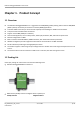
Robustel GoRugged M1000 Pro User Guide Chapter 1. Product Concept 1.1 Overview The Robustel GoRugged M1000 Pro is a rugged serial to GPRS/EDGE gateway offering state‐of‐the‐art GSM/GPRS (EDGE optional) connectivity for machine to machine (M2M) applications. Automatic GPRS connection (no AT commands required) and watchdog for reliable communications. Transparent TCP and UDP socket connections. Support Virtual COM (COM port redirector).
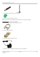
Robustel GoRugged M1000 Pro User Guide y 2‐pin pluggable terminal block for power connector x1 y CD with user guide and configuration utility x1 Note: Please notify your sales representative if any of the above items are missing or damaged.
Robustel GoRugged M1000 Pro User Guide 1.
Robustel GoRugged M1000 Pro User Guide RS‐485 Data+ (A), Data‐ (B), GND Type Dry Contact Mode DI or event counter Dry Contact Digital Input On: short to GND Off: open Isolation 3K VDC or 2K Vrms Counter Frequency 900 Hz Digital Filtering Time Interval Software selectable Over‐voltage Protection 36 VDC Type Sink Mode DO or pulse output Pulse Output Frequency 1 kHz Over‐voltage Protection 40 VDC Over‐current Protection 0.
Robustel GoRugged M1000 Pro User Guide 1.4 Dimensions 1.5 Selection and Ordering Data Please refer to corresponding M1000 Pro datasheet. RT_M1000 Pro_UG_v01.01 Confidential 27.12.
Robustel GoRugged M1000 Pro User Guide Chapter 2. Installation 2.1 Overview 2.2 LED Indicators Name Color Function RSSI (3 LEDs) Green Cellular signal strength level NET Red Please refer to Table ME Functions Indicating the TCP connection status. SYS Green TCP connection established: blinking every 0.3s No TCP connection: blinking every 1.
Robustel GoRugged M1000 Pro User Guide 2 bars 3 bars Average signal (GSM and GPRS connections) Exceptional signal (GSM and GPRS connections) ME Functions NET LED Off 600 ms on / 600ms off 75 ms on / 3 s off 75 ms on / 75 ms off / 75 ms on / 3 s off 500 ms on / 25 ms off On Function ME is in one of the following modes: ‐ POWER DOWN mode ‐ ALARM mode ‐ CHARGE ONLY mode ‐ NON‐CYCLIC SLEEP mode ‐ CYCLIC SLEEP mode with no temporary wake‐up event in progress Limited Network Service: No SIM card inserted o
Robustel GoRugged M1000 Pro User Guide 2.4 Installation the SIM Card Be sure to insert a SIM card before you use the modem. Note: A SIM card set with PIN code cannot be used normally in the modem. You need to use Modem Configurator to unlock the PIN code of the SIM card before using it in the modem. Make sure to disconnect the charger and switch off your modem before inserting or removing your SIM/USIM card. 1. 2. 3. 1. 2. Inserting SIM Card Make sure your charger is disconnected.
Robustel GoRugged M1000 Pro User Guide 2.5 Connect the External Antenna (SMA Type) Connect this to an external antenna with SMA male connector. Make sure the antenna is for the correct frequency as your GSM operator with impedance of 50ohm, and also connector is secured tightly. 2.6 Connect the Modem to External Device User can use the serial cable to connect the modem’s DB9 female connector to external controller / computer.
Robustel GoRugged M1000 Pro User Guide 2.7 Connecting the I/O Device and Sensors Digital Input Dry Contact: Digital Output (Sink Type) 2.8 Grounding the Modem Grounding and wire routing help limit the effects of noise due to electromagnetic interference (EMI). Run the ground connection from the ground screw to the grounding surface prior to connecting devices. Note: This product is intended to be mounted to a well‐grounded mounting surface, such as a metal panel. 2.
Robustel GoRugged M1000 Pro User Guide Chapter 3. Operate the Modem 3.1 Working Mode Overview There are two working modes available in the modem, please read carefully operate the Modem Configurator software: Mode Description When DIP switches to Config Mode, user could use follow functions: 1. Configure modem via Modem Configurator Pro; Config Mode 2. Upgrade firmware. Normal Mode Serial port default parameters: 115200, 8, None, 1 When DIP switches to Normal Mode, user could use follow functions: 1.
Robustel GoRugged M1000 Pro User Guide 3.2.1 Starting Modem Configurator Pro 2. Switch the modem to “Config Mode”, connect the RS‐232 port of the modem to a host PC, then power on the modem. Double click “Modem Configurator Pro.exe” to start the software. 3. Select the correct serial port which is connecting to the modem, then click 1. RT_M1000 Pro_UG_v01.01 Confidential 27.12.2011 button.
Robustel GoRugged M1000 Pro User Guide After that you can see the popup windows “Operation Succeed”. Note: The RS‐232 connector uses the standard PINOUT. A direct male DB9 to female DB9 cable can be used to connect to a PC’s serial port. If you use a USB‐to‐serial product to configure the modem may cause unexpected errors when configuring the modem. Operation Area Introduction Menu Icon Description File‐>Exit Exit the Modem Configurator.
Robustel GoRugged M1000 Pro User Guide Read Write Default Reboot Read modem’s currently settings. Save changes into modem. Note: Reboot for changes to take effect. Set modem to default factory settings, which will take effect after clicking “Write” button. Note: PIN setting, Phone Book settings and COM settings will not be restored to factory default. Reboot the modem. After rebooting, user should disconnect and re‐connect to the RS‐232 port again. Exit Exit the Modem Configurator.
Robustel GoRugged M1000 Pro User Guide 2. Select Import from the Settings menu. Then select a profile. Click on Open. 3. Click “Write” button then it will popup “Import Succeed” windows. 3.2.3 Upgrade Modem Firmware The following instructions illustrate how to use Modem Configurator to upgrade the firmware of a modem. 1. Click “Upgrade” button; 2. Select the firmware from the local PC, then click “Open”; RT_M1000 Pro_UG_v01.01 Confidential 27.12.
Robustel GoRugged M1000 Pro User Guide 3. During upgrading, you can see the progress bar. After upgrading, you can see “Upgrade Finished” popup windows. 4. Reboot the modem manually after upgrading. 3.2.4 Basic This tab allows user to set follow items: Basic Item Device Name Com Type Selection ME Type Description Default Write down the description name of the modem, such as write down Modem the modem installation site name in order to identify each modem. Select from “RS232” and “RS485”.
Robustel GoRugged M1000 Pro User Guide IMEI Password Init. String SIM Card PIN Setup Synchronize with PC Cellular module’s IMEI number. Password for SMS control, including remote configuration and remote reading modem status. The password can be left as null, maximum 20 ASCII characters. User could enter the initial string in the text input box. Note: Maximum 39 characters for each initial string. Select from “Disable PIN Lock” and “Enable PIN Lock”.
Robustel GoRugged M1000 Pro User Guide PPP protocol. This tab allows user to set GPRS and related items for automatic GPRS connection: GPRS Item Description APN Access Point Name for cellular dial‐up connection, provided by local ISP. User Name User Name for cellular dial‐up connection, provided by local ISP. Password Password for cellular dial‐up connection, provided by local ISP. Selected from “Use Peer DNS” and “Manual”. DNS Use Peer DNS: to automatically have DNS server assigned from local ISP.
Robustel GoRugged M1000 Pro User Guide Select from “Always Online” and “Connect On Demand”. Mode @ Always Online: M1000 Pro will automatically a GPRS connection after power on and each Connection restarts, this will remain and will be re‐established after an interruption. Control Connect On Demand: After selection this option, user could configure wakeup at preset time, wakeup by Call, wakeup by SMS, wakeup by local serial port data at Wakeup Tab. Tick to enable.
Robustel GoRugged M1000 Pro User Guide 3.2.6 Advanced 1 Advanced settings part 1 for GPRS and IP communications. Advanced 1 Item Description The serial port will queue the data in the buffer and send the data to the Cellular port when it reaches the Interval Timeout in the field. Interval The units of the timeout is 100ms, default value is 2, which mean the default packet Timeout timeout is 200ms.
Robustel GoRugged M1000 Pro User Guide International Roaming PLMN in SIM Preferred PLMN Online SMS Notification includes follow information: Name: Reg: Operator: RSSI: Local IP: RTC: COM: Note: Local IP is the M1000 Pro’s IP address assigned by ISP when dial‐up to cellular network successful. Tick to enable. Selected from “enable” and “disable.” Enable: international roaming is enabled; Disable: international roaming is disabled.
Robustel GoRugged M1000 Pro User Guide 3.2.7 Advanced 2 Advanced settings part 2 for GPRS and IP communications. Advanced 2 Item Description Default Tick to enable. Some TCP servers required Login Request Packet with follow flow: A TCP connection begins with the client opening a TCP/IP socket to the server and sending a Custom Login Request Packet. If the login request is valid, the server responds with a Login Disable Login Acknowledge Packet and begins sending Sequenced Data Packets.
Robustel GoRugged M1000 Pro User Guide always online. Interval REQ Packet ACK Packet Custom Logout REQ Packet ACK Packet Time interval between two Keep Alive packets, selecting from 5 to 1200 seconds. 40 seconds Keep Alive Request Packet, written in Hex format, maximum 64 bytes. Null Keep Alive Acknowledge Packet, written in Hex format, maximum 32 bytes. Keep Alive Acknowledge Packet is optional. Tick to enable.
Robustel GoRugged M1000 Pro User Guide with preset time schedule every day, support maximum 3 time schedule/day (e.g. 07:00, 11:00 and 23:30 every day). Tick the Periodically Connect Interval checkbox to allow modem Disable Periodically Connect automatic connects to GPRS with preset interval, select from 1 to Interval 1800 minutes. The interval is defined as time interval between two GPRS connections.
Robustel GoRugged M1000 Pro User Guide 3.2.9 Reboot Since cellular network is not as stable as fixed line, M1000 Pro supports various auto reboot function to keep modem working 24x7 without hang up. Reboot Note: This function is available under both “Config Mode” and “Normal Mode”. Item Description Default Tick the Time checkbox to allow modem auto reboot with preset time Disable Time schedule every day, support maximum 3 time schedule/day (e.g. 07:00, 11:00 and 23:30 every day).
Robustel GoRugged M1000 Pro User Guide (e.g. Reboot ok!). Note: Only support text format SMS. Note: 1. Time format for Time reboot is 24‐hours. 2. The phone numbers for Call and SMS function can be set in Phone Book tab. 3. The Caller ID must be written in international format, starting with “+” followed by the country code. 4. If you leave Caller ID blank, the modem will reboot with any incoming call, which may cause unexpected issue. It is highly recommend setting the Call ID. 3.2.
Robustel GoRugged M1000 Pro User Guide It will trigger alarm when counter reaching this figure. After triggering alarm, DI keeps counting but will not trigger alarm again. To clear the counter, use SMS command or Modbus polling command. SMS command: please refer to 5.3 SMS Commands for Remote Control‐>Clear Event Counter Modbus address: please refer to 5.4 Modbus Address Mapping Available when DI under Event Counter mode.
Robustel GoRugged M1000 Pro User Guide This tab describes Digital Output settings. Networks Item Description Digital Output acts according to different alarm source. Selected from DI Alarm, SMS Control, Call Control, selection can be one or more. DI Alarm: Digital Output triggers the related action when there is Alarm Source alarm from Digital Input. SMS Control: Digital Output triggers the related action when receiving SMS from the number in the phone book.
Robustel GoRugged M1000 Pro User Guide High Output Delay DO over TCP generate a square wave as specified in the pulse mode parameters. The low level widths are specified here. Input from 1 to 30000 ms. Available when enable Pulse in Alarm On Action/Alarm Off Action. In Pulse Output mode, the selected digital output channel will generate a square wave as specified in the pulse mode parameters. The high level widths are specified here. Input from 1 to 30000 ms.
Robustel GoRugged M1000 Pro User Guide Tick the SMS Reboot checkbox to allow modem auto reboot with Disable incoming specified short message from this number. Tick the Call Wakeup checkbox to allow modem automatic connects Disable Call Wakeup to GPRS with incoming call from this number. Tick the SMS Wakeup checkbox to allow modem automatic connects Disable SMS Wakeup to GPRS with incoming specified short message from this number.
Robustel GoRugged M1000 Pro User Guide 3.2.14 Networks Networks Item Description SMS Service Center Read the Short Message service center. Registration GSM Operator Cell ID RSSI Update Frequency Show the modem current registration status. There are 3 status: 1. Not registered 2. Registered, home network 3. Registered, roaming Show the modem current registered GSM operator name. Show the modem current register base station cell ID. Show the modem current RSSI from 0 to 31 and corresponding DB.
Robustel GoRugged M1000 Pro User Guide 2. Click “Read” to refresh the “Network” and “Rx Level” status. Values of received signal strength (RSSI) Value of received signal strength indication (RSSI) 0 to 12 13 to 19 20 to 31 99 Interpretation of the received signal strength Insufficient or weak Average Good No signal Note: RSSI should remain higher than 12 to create/accept GSM CSD data calls or establish a GPRS connection.
Robustel GoRugged M1000 Pro User Guide Chapter 4. Typical Applications 4.1 Overview Cellular data transmission is an increasingly attractive mechanism for communication with remote, non‐permanent or mobile devices. Being able to collect and distribute data virtually anywhere without requiring the limitation of working within specific fixed line networks is a powerful force for efficiency and reliability.
Robustel GoRugged M1000 Pro User Guide 4.2 GPRS General When using data services via GPRS, GPRS ISPs offer various contract options, especially regarding the pricing (basic price, basic data volume, billing unit). Please contact the according providers for further information. In general, GPRS ISPs bill every time a connection is terminated and daily at midnight (the ISP will terminate the connection at this time), and all accumulated data are rounded to the billing unit.
Robustel GoRugged M1000 Pro User Guide Exceptions to this restriction will be provided by the according provider, if available. Please also contact your provider to clarify if it is possible to use a public IP or Operator VPN (Virtual Private Network) for possibly required server functionality. 4.2.
Robustel GoRugged M1000 Pro User Guide Note: The above mentioned values represent the theoretically maximum possible values for a GPRS device. For an EDGE device, values four times as large may be assumed. In practice, the following applies: GPRS will not provide guaranteed data rates or bandwidths for the application.
Robustel GoRugged M1000 Pro User Guide Types of TCP Client Connection: 1. Fixed Public IP (or dynamic public IP with domain name) for the host PC The M1000 Pro will only be able to connect to a host PC if the PC is using a fixed public IP address (or dynamic public IP with domain name), M1000 Pro can be any IP (either a private IP or public IP). 2. Connecting TCP client and TCP server within the same cellular service provider.
Robustel GoRugged M1000 Pro User Guide 4.3.3 UDP Mode The main difference between the TCP and UDP protocols is that TCP guarantees delivery of data by requiring the recipient to send an acknowledgement to the sender. UDP does not require this type of verification, making it possible to offer faster delivery. UDP also allows you to unicast data to one IP, or multicast the data to a group of IP addresses. These traits make UDP mode especially well suited for message display applications.
Robustel GoRugged M1000 Pro User Guide Chapter 5. Appendix 5.1 Factory Settings Factory setting of the modem COM port under Config Mode and Normal Mode is: Data bits = 8 Parity = none Stop bits = 1 Baud = 115200 bps Flow control = none 5.2 Restore to Factory Default The modem could be restored to factory default by Modem Configurator Pro, SMS or hardware operation. Following steps indicate how to restore to factory default by hardware operation: 1. Set the modem under Config Mode, power on the modem; 2.
Robustel GoRugged M1000 Pro User Guide modem to take effect with command 0004. Cmd Description Syntax Control Commands Comments 0000 if no password, please use command "cmd", or use command "password:cmd" if there is a password. Following commands are the same.
Robustel GoRugged M1000 Pro User Guide 1009 Set Socket Mode 1010 1011 Set Center IP Set Center Port cmd,ip cmd,port 1012 Set Connection Mode cmd,mode,flag 1013 1014 1015 cmd,time cmd,retries cmd,interval cmd,timeout timeout: (2 ‐ 100)* 100ms 1017 Set Inactivity Time Set Connection Max Retries Set Connection Interval Set Data Packing Interval Timeout Set Packet Length dns1(ip address, such as: 192.168.0.1) dns2(ip address, such as: 192.168.0.
Robustel GoRugged M1000 Pro User Guide 1024 Set Custom Login cmd,flag,retries,interval,request,ackno wledge 1025 Set Custom Keep Alive cmd,flag,interval,request,acknowledge 1026 Set Custom Logout cmd,flag,request,acknowledge 1027 Set Time Wakeup cmd,flag,time1,time2,time3 1028 Set Periodically Connect cmd,flag,interval 1029 Set Call Wakeup cmd,flag1,flag2,content RT_M1000 Pro_UG_v01.01 Confidential 27.12.
Robustel GoRugged M1000 Pro User Guide 1030 Set SMS Wakeup cmd,flag1,flag2,passwd,content 1031 Set Serial Data Wakeup cmd,flag 1032 Set Data To Com After cmd,content Online content(max 30 bytes) 1033 Set Time Reboot cmd,flag,time1,time2,time3 1034 Set Call Reboot cmd,flag1,flag2,content 1035 Set SMS Reboot cmd,flag1,flag2,passwd,content 1036 Set Singal Update Frequency cmd,value 1037 Set Phone Number cmd,index,number,flag RT_M1000 Pro_UG_v01.
Robustel GoRugged M1000 Pro User Guide 1038 Set Phone Group cmd,index,flag 1039 Set DI Parameters cmd,mode,filtering,trigger,active,flag,m essage1,message2,group,DIOverTcp RT_M1000 Pro_UG_v01.01 Confidential 27.12.2011 book isn't full) number(max 20 bytes) flag: xxxxx (binary format: 00000 ‐ 11111) flag.1: 0 ‐ disable call reboot 1 ‐ enable call reboot flag.2: 0 ‐ disable call wakeup 1 ‐ enable call wakeup flag.3: 0 ‐ disable sms reboot 1 ‐ enable sms reboot flag.
Robustel GoRugged M1000 Pro User Guide 1040 Set DO Parameters cmd,flag,onAction,offAction,flag1,keep On,DOOverTcp 1041 Set Pulse Parameters cmd,low,high,output,delay RT_M1000 Pro_UG_v01.01 Confidential 27.12.2011 (max 70 bytes) *message2: alarm off message (max 70 bytes) *group: 1 ‐ 10 (phone group) *DIOverTcp: 0 ‐ disable 1 ‐ enable flag: xxxx (binary format: 000 ‐ 111) flag.0 : 0 ‐ disable DI alarm control DO output 1 ‐ enable DI alarm control DO output flag.
Robustel GoRugged M1000 Pro User Guide 1042 Set DO SMS Parameters Control cmd,onContent,offContent,group high: 1 ‐ 30000 output: 0 ‐ 30000 delay: 0 ‐ 30000 *onContent: max 70 bytes *offContent: max 70 bytes group: 1 ‐ 10 (phone group) Get Commands 2000 Get Base Parameters cmd 2001 Get GPRS Parameters cmd 2002 Get Data Packing Parameters cmd 2003 Get Login Parameters cmd RT_M1000 Pro_UG_v01.
Robustel GoRugged M1000 Pro User Guide 2004 Get Wakeup Parameters cmd 2005 Get Reboot Parameters cmd 2006 Get Phone Number Parameters cmd 2007 Get Firmware Version cmd 2008 Get Phone Parameters 2009 Get DI Parameters Group return: 1 ‐ time wakeup 2 ‐ call wakeup 3 ‐ sms wakeup 4 ‐ data wakeup return: 1 ‐ time reboot 2 ‐ call reboot 3 ‐ sms reboot return: index,number,call reboot,call wakeup,sms reboot,sms wakeup,sms control return: firmware version return: index: phone group index flag: xx
Robustel GoRugged M1000 Pro User Guide 4. Enable International Roaming a. Enable International Roaming, corresponding command is: 1023,1 b. Disable International Roaming, use PLMN in SIM, corresponding command is: 1023,0,0 or 1023,0 c. Disable International Roaming, manual, plmn = 46002, corresponding command is: 1023,0,1,46002 5. Set Custom Login a.
Robustel GoRugged M1000 Pro User Guide 5.5 Robustel DI and DO over TCP Protocol DI over TCP and DO over TCP are using private protocol. User can easily integrate Robustel DI and DO over TCP Protocol into their SCADA or system.
Robustel GoRugged M1000 Pro User Guide 5.6 Troubleshooting This section of the document describes possible problems encountered when using the Robustel M1000 Pro modem and their solutions. 5.6.1 The modem’s LED does not light: Check if modem has connected to a 9 to 36VDC power supply properly. Check if the power connector is properly inserted. 5.6.2 M1000 Pro keep rebooting all the time: Please make sure you have inserted the SIM card. 5.6.
Robustel GoRugged M1000 Pro User Guide CHAP CSD CTS dB dBi DC DCD DCE DCS 1800 DSR DTE DTMF DTR EMC EMI ESD ETSI GND GPRS GSM IMEI kbps LED MAX Min MO MS MT PAP PC PCN PCS PDU PPP PIN PSU PUK R&TTE RF RTC RTS Rx Challenge Handshake Authentication Protocol Circuit Switched Data Clear to Send Decibel Decibel Relative to an Isotropic radiator Direct Current Data Carrier Detect Data Communication Equipment (typically modems) Digital Cellular System, also referred to as PCN Data Set Ready Data Terminal Equipme
Robustel GoRugged M1000 Pro User Guide SIM SMA SMS TCP/IP TE Tx UART UDP USSD VSWR Subscriber Identification Module Subminiature Version A RF Connector Short Message Service Transmission Control Protocol / Internet Protocol Terminal Equipment, also referred to as DTE Transmit Direction Universal Asynchronous Receiver‐transmitter User Datagram Protocol Unstructured Supplementary Service Data Voltage Stationary Wave Ratio RT_M1000 Pro_UG_v01.01 Confidential 27.12.