Robustel GoRugged M1000 Pro V2 Dual SIM Industrial Serial to Cellular Gateway For GSM/GPRS/EDGE/UMTS Networks User Guide Document Name: User Guide Firmware: 1.0.8 M1000 Pro V2 Configurator: 1.0.8 Date: 2012-11-23 Status: / Confidential Doc ID: RT_M1000_Pro V2_v01.00 www.robustel.
Robustel GoRugged M1000 Pro V2 User Guide About This Document This document describes the hardware and software of the Robustel M1000 Pro V2 Dual SIM Industrial Serial to Cellular Gateway. Copyright© Guangzhou Robustel Technologies Co., Limited All Rights Reserved. Trademarks and Permissions Robustel are trademark of Guangzhou Robustel Technologies Co. Limited. All other trademarks and trade names mentioned in this document are the property of their respective holders.
Robustel GoRugged M1000 Pro V2 User Guide Important Notice Due to the nature of wireless communications, transmission and reception of data can never be guaranteed. Data may be delayed, corrupted (i.e., have errors) or be totally lost.
Robustel GoRugged M1000 Pro V2 User Guide Do not drop, hit or shake the gateway. Do not use the gateway under extreme vibrating conditions. Do not pull the antenna or power supply cable. Attach/detach by holding the connector. Connect the gateway only according to the instruction manual. Failure to do it will void the warranty. In case of problem, please contact authorized distributor. RT_M1000 Pro V2_UG_v01.00 Confidential 23.11.
Robustel GoRugged M1000 Pro V2 User Guide Regulatory and Type Approval Information Table 1: Directives 2002/95/EC Directive of the European Parliament and of the Council of 27 January 2003 on the restriction of the use of certain hazardous substances in electrical and electronic equipment (RoHS) 2002/96/EC Directive of the European Parliament and of the Council on waste electrical and electronic equipment (WEEE) 2003/108/EC Directive of the European Parliament and of the Council of 8 December 2003 ame
Robustel GoRugged M1000 Pro V2 User Guide Revision History Updates between document versions are cumulative. Therefore, the latest document version contains all updates made to previous versions. Release Date Firmware Version Details 2012-11-23 1.00 First Release RT_M1000 Pro V2_UG_v01.00 Confidential 23.11.
Robustel GoRugged M1000 Pro V2 User Guide Contents Chapter 1. Product Concept ................................................................................................................................... 8 1.1 Overview .............................................................................................................................................. 8 1.2 Packing List ............................................................................................................................
Robustel GoRugged M1000 Pro V2 User Guide 4.2.4 Virtual COM Mode ....................................................................................................................... 46 Chapter 5. Appendix ............................................................................................................................................ 47 5.1 Factory Settings................................................................................................................................... 47 5.
Robustel GoRugged M1000 Pro V2 User Guide Chapter 1. Product Concept 1.1 Overview Robustel GoRugged M1000 Pro V2 is a rugged serial to cellular gateway with dual SIM offering state-of-the-art 2G connectivity for machine to machine (M2M) applications. Dual SIM redundancy for continuous cellular connections. Automatic GPRS/UMTS connection (no AT commands required) and watchdog for reliable communications. Transparent TCP and UDP socket connections.
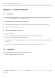
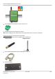
Robustel GoRugged M1000 Pro V2 User Guide 2-pin pluggable terminal block for power connector x1 CD with user guide and configuration utility x1 Note: Please notify your sales representative if any of the above items are missing or damaged. Optional accessories (can be purchased separately): SMA antenna (Stubby antenna or Magnet antenna optional) x1 Stubby antenna Magnet antenna Serial cable for RS232 (DB9 Female to DB9 Male, 1 meter) x1 Wall Mounting Kit RT_M1000 Pro V2_UG_v01.
Robustel GoRugged M1000 Pro V2 User Guide 35mm Din-Rail mounting kit AC/DC Power Supply Adapter (12VDC, 1A) x1 1.3 Key Features Dual SIM redundancy for continuous cellular connections. Auto GPRS/UMTS connect/reconnect (no AT commands required), watchdog for reliable communications. Transparent TCP and UDP socket connections. Supports Virtual COM (COM port redirector). Supports ICMP, DDNS. Supports Modbus/RTU to Modbus/TCP.
Robustel GoRugged M1000 Pro V2 User Guide 1.4 Specifications Cellular Interface Standards: GSM/GPRS/EDGE GPRS: max. 86 kbps (DL & UL), class 10 EDGE: max. 236.8 kbps (DL & UL), class 12 UMTS: max. 384 kbps (DL/UL) Frequency: 850/900/1800/1900 MHz for GPRS/EDGE 900/2100 MHz for UMTS CSD: Up to 14.4 kbps Output Power: 1 watt GSM1800/1900 2 watts EGSM 900/GSM 850 SIM: 2 x (3V & 1.
Robustel GoRugged M1000 Pro V2 User Guide 1.5 Dimensions 1.6 Selection and Ordering Data Please refer to corresponding M1000 Pro V2 datasheet. RT_M1000 Pro V2_UG_v01.00 Confidential 23.11.
Robustel GoRugged M1000 Pro V2 User Guide Chapter 2. Installation 2.1 Overview SIM Cover 2.2 LED Indicators Name Color RSSI (3 LEDs) Green NET Red SYS Green PWR Green Function Cellular signal strength level Indicating the GPRS/UMTS connection status. GPRS/ UMTS connection established: blinking every 3s GPRS/ UMTS connection alarm: always on Wireless module rebooting and searching GPRS/UMTS network: blinking every 1s Indicating the system status. System is booting: blinking every 0.
Robustel GoRugged M1000 Pro V2 User Guide RSSI LEDs None 1 bar (Only the first LED is on) 2 bars (The first and the second LED are on) 3 bars (All the RSSI LEDs are on) The first and the second LED are blinking every 1 second The third LED is blinking every 1 second The second LED is blinking every 1 second The third LED is blinking every 1 seconds The first and the third LED are blinking every 1 second 2.
Robustel GoRugged M1000 Pro V2 User Guide 2.4 Installation the SIM Card Be sure to insert a SIM card before you use the gateway. Note: A SIM card set with PIN code cannot be used normally in the gateway. You need to use DTU Configurator to unlock the PIN code of the SIM card first. Make sure to disconnect the charger and switch off your gateway before inserting or removing your SIM/USIM card. 1. 2. 3. 1. 2. Inserting SIM Card Make sure your charger is disconnected.
Robustel GoRugged M1000 Pro V2 User Guide 2.5 Connect the External Antenna (SMA Type) Connect this to an external antenna with SMA male connector. Make sure the antenna is for the correct frequency as your GSM operator with impedance of 50ohm, and also connector is secured tightly. 2.6 Connect the Gateway to External Device User can use the serial cable to connect the gateway’s DB9 female connector to external controller / computer.
Robustel GoRugged M1000 Pro V2 User Guide 2.7 Grounding the Gateway Grounding and wire routing help limit the effects of noise due to electromagnetic interference (EMI). Run the ground connection from the ground screw to the grounding surface prior to connecting devices. Note: This product is intended to be mounted to a well-grounded mounting surface, such as a metal panel. 2.8 Power Supply The power supply range is 9 to 36VDC.
Robustel GoRugged M1000 Pro V2 User Guide Chapter 3. Operate the Gateway 3.1 Working Mode Overview There are two working modes available in the gateway, please read carefully operate the DTU Configurator software: Mode Description When DIP switches to Config Mode, user could use follow functions: 1. Configure gateway via DTU Configurator ; Config Mode 2. Upgrade firmware.
Robustel GoRugged M1000 Pro V2 User Guide 3.2.1 Management via RS-232 port 1. 2. Switch the gateway to “Config Mode”, connect the RS-232 port of the gateway to a host PC, and then power on the gateway. Double click “DTU Configurator.exe” to start the software. RT_M1000 Pro V2_UG_v01.00 Confidential 23.11.
Robustel GoRugged M1000 Pro V2 User Guide 3. Click on the operation area, you can see the popup window as below: 4. Select “Serial” and the correct COM port which is connecting to the gateway in the drop down boxes. Then click “OK”. Note: Serial is the default management mode of DTU configurator. 5. Select the correct COM port, then click button. After that you can see the popup windows “Operation Succeed”. Note: The RS-232 connector uses the standard PINOUT.
Robustel GoRugged M1000 Pro V2 User Guide 3.2.2 Management via TCP connection 1. Double click “DTU Configurator.exe” to start the software. 2. Click 3. Select “TCP” and the correct mode in the drop down boxes, and enter the local TCP port. If you choose client mode, you need to enter the remote gateway’s IP address. Then click “OK”. 4. Click on the operation area, you can see the popup window as below: button.
Robustel GoRugged M1000 Pro V2 User Guide 5. After that you can see the popup windows “Operation Succeed”. 3.2.3 Operation Area Introduction Menu Icon Description File->Exit Exit the DTU Configurator. settings->Communication Set the communication ways of configurator: Serial or TCP. Settings->Export Export the gateway’s current configuration file to your local PC. Settings->Import Import the gateway’s configuration file from local PC to the gateway.
Robustel GoRugged M1000 Pro V2 User Guide Connect Disconnect Connect the DTU Configurator to the gateway, which will use the PC’s local RS-232 port. Disconnect the DTU Configurator to the gateway and release the PC’s RS-232 port. Read Read gateway’s current settings. Write Save changes into gateway. Note: Some parameters changes need to reboot to take effect. Default Set gateway to default factory settings. Reboot Reboot the gateway.
Robustel GoRugged M1000 Pro V2 User Guide 2. Select Import from the Settings menu. Then select a profile. Click on Open. 3. Click “Write” button then it will popup “Import Succeed” windows. 3.2.5 COM This tab allows user to set the parameters of serial com port: Basic Item Description COM Type Select from “RS232” and “RS485”. RT_M1000 Pro V2_UG_v01.00 Confidential 23.11.
Robustel GoRugged M1000 Pro V2 User Guide Baud Rate Data Bits Flow Ctrl Parity Stop Bits Interval Timeout Packet Length Delimiter Delimiter Process Select from “1200”, “2400”, “4800”, “9600”, “19200”, “38400”, “57600” and “115200”. Select from “7” and “8”. Select from “None” and “Hardware”. Select from “None”, “Odd”, “Even”, “Mark” and “Space”. Select from “1” and “2”.
Robustel GoRugged M1000 Pro V2 User Guide Item Device Name SMS Control Password SMS Ctrl Phone Group SIM Card PIN Setup Description Write down the description name of the gateway, such as write down the gateway installation site name in order to identify each gateway. Password for SMS control, including remote configuration and remote reading gateway status. The password can be left as null, maximum 20 ASCII characters.
Robustel GoRugged M1000 Pro V2 User Guide Traditional GPRS gateway can only dialup to internet via external PPP enabled host device such as PC, PLC with built-in PPP protocol. This tab allows user to set GPRS/UMTS and related items for automatic GPRS/UMTS connection: GPRS Item Description APN Access Point Name for cellular dial-up connection, provided by local ISP. Auth Type Selected from “None” , “Auto”, “PAP” and “CHAP” as the local ISP required.
Robustel GoRugged M1000 Pro V2 User Guide 3.2.8 Dual SIM This tab allows user to set the SIM cards’ priorities, backup policies and other related parameters. Dual SIM Item Description Preferred SIM Set the preferred SIM card from SIM 1 or SIM 2. Set revert back policies when the gateway work with the backup SIM card. Auto Failover: Gateway will revert back to preferred SIM card when dial up failed or according to the failover policy you select.
Robustel GoRugged M1000 Pro V2 User Guide 3.2.9 Connection This tab allows user to set the TCP/UDP connections and other related parameters. Connection Item Description Selected from “TCP Client”, “TCP Server” and “UDP”. TCP Client: Gateway works as TCP client, initiate TCP connection to TCP server, the server Mode @ address supports both IP and domain name. Socket TCP Server: Gateway works as TCP server, listening for connection request from TCP Application client. UDP: Gateway works as UDP client.
Robustel GoRugged M1000 Pro V2 User Guide Connection Control Always Online: Gateway will automatically a GPRS/UMTS connection after power on and each restarts, this will remain and will be re-established after an interruption. Connect On Demand: After selection this option, user could configure wakeup at preset time, wakeup by Call, wakeup by SMS, wakeup by local serial port data at Wakeup Tab.
Robustel GoRugged M1000 Pro V2 User Guide 3.2.10 DDNS This tab allows user to set the DDNS server and other related parameters. DDNS Item Description Selected from None, dyndns, 3322 and No-IP. Server None: Disable DDNS function. dyndns, 3322 and No-IP: Corresponding to three DDNS service providers. Host Enter the Host name the DDNS server provided. User Name Enter the user name the DDNS server provided. Password Enter password the DDNS server provided.
Robustel GoRugged M1000 Pro V2 User Guide 3.2.11 Phone Book This tab allows user to set the phone numbers and which phone group they are belonged to. Phone Book Item Description Default Phone NO. Input the telephone number. Null Select different phone numbers to include them in the same phone Null Phone Group group. Note: The Phone NO. must be written in international format, starting with “+” followed by the country code. 3.2.
Robustel GoRugged M1000 Pro V2 User Guide Wakeup Item Description Default Tick the Time checkbox to allow gateway automatic connects to Disable Time GPRS/UMTS with preset time schedule every day, support maximum 3 time schedule/day (e.g. 07:00, 11:00 and 23:30 every day). Tick the Periodically Connect Interval checkbox to allow gateway Disable automatic connects to GPRS/UMTS with preset interval, select from 1 Periodical to 1800 minutes.
Robustel GoRugged M1000 Pro V2 User Guide 3.2.13 Reboot Since cellular network is not as stable as fixed line, M1000 Pro V2 supports various auto reboot function to keep gateway working 24x7 without hang up. Reboot Note: This function is available under both “Config Mode” and “Normal Mode”. Item Description Default Tick the Time checkbox to allow gateway auto reboot with preset time Disable Time schedule every day, support maximum 3 time schedule/day (e.g. 07:00, 11:00 and 23:30 every day).
Robustel GoRugged M1000 Pro V2 User Guide SMS Phone Group @ SMS Password Enable SMS Reply Tick the SMS checkbox to allow gateway auto reboot with incoming specified short message from specified Caller ID (phone number). Specified short message is set at Password item. (e.g. reboot) The Caller ID (phone number) should be specified in Phone Book tab by inputting the phone number and tick SMS Reboot checkbox. Set the Phone Group which was allowed to reboot the gateway by SMS.
Robustel GoRugged M1000 Pro V2 User Guide Mode Selected from Slave and Master. Slave: Selected when gateway connect to Modbus slave device with serial COM port. Master: Selected when gateway connect to Modbus Master device with serial COM port. Slave Note: Generally, If you select Slave mode, gateway need to work under TCP server mode, and If you select Master mode, gateway need to work under TCP client mode. Available when enable Modbus Gateway and select Master mode.
Robustel GoRugged M1000 Pro V2 User Guide 3.2.15 Advanced Advanced settings for GPRS/UMTS and IP communications. Advanced Item Description Tick to enable. Some TCP servers required Login Request Packet with follow flow: A TCP connection begins with the client opening a TCP/IP socket to the server and sending a Custom Login Request Packet. If the login request is valid, the server responds with a Login Login Acknowledge Packet and begins sending Sequenced Data Packets.
Robustel GoRugged M1000 Pro V2 User Guide When using GPRS/UMTS with a session running most ISPs will monitor the traffic flow, if there is none for a predetermined period of time then it will shut the connection down at Custom either the DHCP server or the APN, this is performed so that system resources are not taken Keep Alive up unnecessarily. To stop this happening you will need to send periodic Keep Alive bytes to keep the modem always online.
Robustel GoRugged M1000 Pro V2 User Guide 3.2.16 NMS This tab allows user to set the related parameters of TCP Network Management. NMS Item Enable Mode Address Port Description Tick this checkbox to enable NMS. Non-configurable. Normally, gateway works under TCP server mode for NMS function, but it also can work under TCP client mode. Please refer to 3.2.2 Management via TCP connection to get the detail information. Non-configurable. Set the listening port of TCP server for NMS function.
Robustel GoRugged M1000 Pro V2 User Guide SIM Update Update the FW of gateway via serial port or TCP connection. The update steps are as bellow: 1. Click “load” button and select the FW file in your computer; 2. Click “Start” button to get started, then you can see a process bar; 3. The updating will last for several minutes, then you will see a pop window to indicate the updating is successful. RT_M1000 Pro V2_UG_v01.00 Confidential 23.11.
Robustel GoRugged M1000 Pro V2 User Guide Chapter 4. Typical Applications 4.1 Overview Cellular data transmission is an increasingly attractive mechanism for communication with remote, non-permanent or mobile devices. Being able to collect and distribute data virtually anywhere without requiring the limitation of working within specific fixed line networks is a powerful force for efficiency and reliability.
Robustel GoRugged M1000 Pro V2 User Guide 4.2 Typical Applications 4.2.1 TCP Client Mode In TCP Client mode, the gateway can actively establish a TCP connection to a pre-defined host computer when serial data arrives. After the data has been transferred, the gateway can automatically disconnect from the host computer by using the Inactivity time settings.
Robustel GoRugged M1000 Pro V2 User Guide these parameters of SIM 2. Then click . 4. Turn to Connection tap. Select Socket Application Mode as TCP Client. Input remote TCP server’s address and port. Select Connection Control Mode as Always Online or Connect On Demand as your need. Then click . 5. Turn the gateway back to Normal mode and reboot it. RT_M1000 Pro V2_UG_v01.00 Confidential 23.11.
Robustel GoRugged M1000 Pro V2 User Guide 4.2.2 TCP Server Mode In TCP Server mode, the serial port on the gateway is assigned a port number. The host computer initiates contact with the gateway, establishes the connection, and receives data from the serial device. As illustrated in the figure, data transmission proceeds as follows: The host requests a connection from the gateway, which is configured for TCP Server mode.
Robustel GoRugged M1000 Pro V2 User Guide 4. Turn to Connection tap. Select Socket Application Mode as TCP Server. Input local listening port. Select Connection Control Mode as Always Online or Connect On Demand as your need. Then click . 5. Turn the gateway back to Normal mode and reboot it. 4.2.3 UDP Mode The main difference between the TCP and UDP protocols is that TCP guarantees delivery of data by requiring the RT_M1000 Pro V2_UG_v01.00 Confidential 23.11.
Robustel GoRugged M1000 Pro V2 User Guide recipient to send an acknowledgement to the sender. UDP does not require this type of verification, making it possible to offer faster delivery. UDP also allows you to unicast data to one IP, or multicast the data to a group of IP addresses. These traits make UDP mode especially well suited for message display applications. 1.
Robustel GoRugged M1000 Pro V2 User Guide The main challenges arise in two other areas: the network connection to the device server and the behavior of the device server. These issues are described in the Technology section below. Chapter 5. Appendix 5.1 Factory Settings Factory setting of the modem COM port under Config Mode and Normal Mode is: Data bits = 8 Parity = none Stop bits = 1 Baud = 115200 bps Flow control = none 5.
Robustel GoRugged M1000 Pro V2 User Guide Check if the SIM card balance is enough or not. 5.
Robustel GoRugged M1000 Pro V2 User Guide PCS PDU PPP PIN PSU PUK R&TTE RF RTC RTS Rx SIM SMA SMS TCP/IP TE Tx UART UDP USSD VSWR Personal Communication System, also referred to as GSM 1900 Protocol Data Unit Point-to-point Protocol Personal Identity Number Power Supply Unit Personal Unblocking Key Radio and Telecommunication Terminal Equipment Radio Frequency Real Time Clock Request to Send Receive Direction Subscriber Identification Module Subminiature Version A RF Connector Short Message Service Transm