ACCU-CHEK Inform II BLOOD GLUCOSE MONITORING SYSTEM Operator’s Manual ®
Manual version Revision date Version 1.0 2008-01 New document Version 2.0 2009-08 Update, new SW version 02.00 Version 3.0 2010-09 Update, new SW version 03.
ACCU-CHEK Inform II System ® Operator’s Manual ©2010 Roche Diagnostics. All rights reserved.
©2010, Roche Diagnostics. All rights reserved. The contents of this document, including all graphics, are the property of Roche Diagnostics. Information in this document is subject to change without notice. Roche Diagnostics shall not be liable for technical or editorial errors or omissions contained herein. No part of this document may be reproduced or transmitted in any form or by any means, electronic or mechanical, for any purpose, without the express written permission of Roche Diagnostics.
1 Introduction 9 Before you start........................................................................................................................................... 9 Intended use ........................................................................................................................................ 9 Important information regarding use ......................................................................................... 9 If you need help .......................................
3 Patient Glucose Testing 33 Information regarding blood glucose testing ................................................................................ 33 Preparing to test ............................................................................................................................... 33 Performing a patient glucose test...................................................................................................... 34 Overview of test procedure .......................................
Linearity Testing Information regarding linearity tests................................................................................................. Linearity testing intervals .............................................................................................................. Information stored during linearity testing............................................................................. Linearity test kit .............................................................................
10 Maintenance and Care Conditions for storage and shipping ............................................................................................. General operating conditions ................................................................................................... Storage .............................................................................................................................................. Cleaning.....................................................................
Introduction 1 Introduction Before you start Intended use The Accu-Chek® Inform II system is intended for in vitro diagnostic use in the quantitative determination of blood glucose levels in venous, capillary, arterial, and neonatal whole blood samples for monitoring blood glucose. The system is indicated for use by healthcare professionals.
Introduction If you need help Information about using the system, the screen menus and performing a test can be found in this operator's manual. Error messages that appear on-screen include information or instructions on how to correct the error. For all questions about the Accu-Chek Inform II system that are not answered in this manual, contact your Roche representative (see Chapter 12).
Introduction What can the system do for you? The Accu-Chek Inform II system has the following features and properties: ■ Perform patient blood glucose tests and glucose control tests with control solution. ■ Automatically record all relevant data for the application.
Introduction Safety information and additional information This section explains how safety-related messages and information related to the proper handling of the system are presented in the Accu-Chek Inform II manual. Please read these passages carefully.
Introduction Important information regarding safety Operator qualification Only trained healthcare professionals may operate the Accu-Chek Inform II system. Operators must also have received comprehensive instruction in the operation, quality control, and care of the Accu-Chek Inform II system. WARNING Protection against infection There is a potential risk of infection.
Introduction Product safety Observe the following information to ensure product safety: ■ The system is suitable for continuous operation. NOTICE The system is not protected against the harmful ingress of fluids (IP X0 rating according to IEC 60529). NOTICE Clean the system only with the solutions recommended. Using other solutions may result in incorrect operation and possible failure of the system. Make sure that the meter and base unit are thoroughly dried after cleaning or disinfecting.
Introduction Battery Pack The meter contains a rechargeable battery pack that begins charging as soon as it is placed in an active base unit (i.e., one connected to a power supply). NOTICE Use only the specially designed battery pack provided by Roche Diagnostics. Using any other type of battery may damage the system. Observe the following general safety instructions for handling batteries: Do not dispose of the battery pack with normal domestic waste.
Introduction Touchscreen NOTICE Laser scanner ■ Use only your finger to touch the screen elements. Using a sharp-edged object (e.g., tip of a pen) can damage the touchscreen. ■ Do not use the system in direct sunlight. Direct sunlight may reduce the life expectancy and functionality of the display, as well as the integrity of test strips. The built-in barcode scanner emits a laser beam when activated. The built-in barcode scanner is a Class 1 laser, according to IEC 60825-1/A2:2001.
Introduction Radiofrequency radiation exposure information Glossary: “FCC” stands for “Federal Communications Commission” (USA). ■ “RSS” stands for “Radio Standards Specification” (Canada) ■ Note: The following table provides an overview of the classifications for electromagnetic compliance (EMC, according to CISPR 11) for different combinations of Accu-Chek Inform II system components. Refer to the explanatory texts following the table for more information on these classifications. Classification acc.
Introduction This device complies with Part 15 of the FCC Rules and with RSS-210 of Industry Canada. Operation is subject to the following two conditions: (1) this device may not cause harmful interference, and (2) this device must accept any interference received, including interference that may cause undesired operation. The Accu-Chek Inform II system complies with the emission and immunity requirements described in IEC 613262-6:2006. It has been designed and tested to CISPR 11 Class B.
Introduction Note on systems with older hardware WARNING Possibility of Electromagnetic Interference Under certain conditions, a specific combination of hardware equipment may emit electromagnetic radiation of such high energy that it can interfere with the proper functioning of other electronic or medical equipment.
Introduction This equipment has been tested and found to comply with the limits for a Class A digital device, pursuant to Part 15 of the FCC Rules. These limits are designed to provide reasonable protection against harmful interference when the equipment is operated in a commercial environment. This equipment generates, uses and can radiate radio frequency energy and, if not installed and used in accordance with the instruction manual, may cause harmful interference to radio communications.
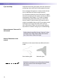
Introduction System components The Accu-Chek Inform II system includes the following components and accessories: A A Meter B Code key reader C Base unit with power supply D Accessory box (shown with consumables, not included) B The system can be configured by two different methods: C 1 Configuration via the Setup function on the meter (see Chapter 9) 2 Configuration via data management system Note: Not all options can be configured using the Setup function on the meter.
Introduction Overview of the meter 1 The meter has the following elements: 1 Test strip port Insert the test strip here. 2 Touchscreen (touch-sensitive display) This screen allows you to perform patient tests, perform controls tests, and review results. To select any of these functions, simply touch the button on the screen. 3 On/Off button Press this button to turn the meter on or off. 4 Barcode scanner (laser) The integrated barcode scanner can be used to read operator and patient IDs.
Introduction Overview of the code key reader 13 12 Test strip vials include a code key.1 This code key is read by the code key reader and the data is sent to the meter. For additional information about the code key reader, see Chapter 6. The code key reader has the following elements: 11 Code key slot 12 LED for displaying status 13 Infrared window for transmitting the code file to the meter 11 Do not exchange code keys while the Code Key Reader is still flashing.
Introduction Overview of the base unit To provide flexibility in line with customer requirements, two versions of the base unit are available. 14 15 ■ The Accu-Chek Inform II Base Unit ■ The Accu-Chek Inform II Base Unit Light Both versions of the base unit can: ■ 16 19 20 17 charge the meter battery pack. In addition, the Accu-Chek Inform II Base Unit also supports: ■ communication with a data management system. ■ communication with a computer.
Introduction Electrical connections are located on the back of the base unit (for a better view the removable wall mount is shown as transparent). For instructions on connecting the base unit, see Chapter 9. Overview of the accessory box The accessory box provides an area for storing and transporting consumables needed for performing point-ofcare blood glucose tests.
Introduction Instructions for initial setup The meter must be configured prior to initial use. During this setup, the following parameters are configured: ■ Date and time format ■ Input mode for Patient ID ■ Input mode for Operator ID ■ Glucose controls: Type and schedule ■ Results screen for glucose control ■ Comments for entry after a test ■ Settings for data transfer You can perform these settings on a limited basis directly in the Setup Menu of the meter.
Powering Up and Entering an Operator ID 2 Powering Up and Entering an Operator ID Powering up the meter 1 Press and release the On/Off button is now on. 2 The Power Up screen appears. 3 Check in the Power Up screen whether the date (lower left) and time (upper right) are displayed correctly. If necessary, refer to the instructions for updating these settings in Chapter 9. Power Up Performing self-checks... .
Powering Up and Entering an Operator ID Adjusting the display Display 12:48pm Using the Display options, you can adjust display parameters to your needs: ■ Adjust the display contrast to the ambient light conditions. ■ Set the time interval for activating the Low Power Mode, which reduces the display contrast after a configurable time without activity (e.g., touching the screen) to conserve energy. 1 In the Power Up screen, touch Contrast. The Display screen appears.
Powering Up and Entering an Operator ID Enabling/disabling the RF card If the unit is equipped with an RF card, you can temporarily enable or disable this functionality as required. The RF card is automatically reactivated the next time you power on the meter. You can then disable it again temporarily, if required.
Powering Up and Entering an Operator ID Closing startup Once you have completed all the necessary changes, ■ touch to proceed to the screen used to enter the operator ID, or ■ wait 5 seconds and the meter automatically proceeds to the screen used to enter the operator ID. Entering the operator ID How and when an operator ID is entered and if a password is required, depends on the configuration of the system. It is also, for example, possible to require the operator ID only when starting control tests.
Powering Up and Entering an Operator ID Entering an operator ID with barcode scanner Operator ID When the screen for entering the operator ID is displayed: 12:48pm 1 2 3 4 5 6 7 8 9 0 A-O 03/16/10 1 Press and release . The button now appears with a black background (during the scan). 2 Hold the meter so that the window of the barcode scanner is approx. 10-20 cm (4-8 in) above the barcode you wish to read. The meter beeps once the barcode has been read successfully.
Powering Up and Entering an Operator ID Entering the operator ID manually Operator ID 12:48pm When the screen for entering the operator ID is displayed: Operator ID 12:48pm MARIA Operator ID 12:48pm MARIA S. 1 2 3 A B C D E P Q R S T 4 5 6 F G H I J U V W X Y 7 8 9 K L M N O Z . - 0 A-O 123 P-Z 123 A-O 03/16/10 03/16/10 03/16/10 1 Touch the letters or numbers to enter the ID.
Patient Glucose Testing 3 Patient Glucose Testing Information regarding blood glucose testing Preparing to test Power Up The following requirements must be met before you can perform a test: 12:48pm ■ The Accu-Chek Performa or Accu-Chek Inform II test strips are available. ■ At least one code file for test strips must be stored in the meter and match the lot number of the test strips used (see Chapter 6).
Patient Glucose Testing Performing a patient glucose test Overview of test procedure A patient glucose test comprises the following steps: ■ Enter the patient ID. This can be done either manually or by using the barcode scanner. ■ Confirm that the code key matches the test strips in use (if configured). ■ Perform the test. As mentioned previously, the following steps must be completed already: Entering or selecting the patient ID Main Menu 12:48pm 1 The meter is switched on.
Patient Glucose Testing You now have three different options, depending on setup, for assigning the subsequent test to a patient. The patient ID function can be configured by your system administrator to: Enter any combination of up to 20 alphanumeric characters, with specified minimum and maximum lengths. Alphanumeric characters are any combination of A - Z and 0 - 9, additionally “.” (period), or “-” (hyphen) may be used. ■ ■ ■ Enter patient ID via barcode scanner. Select a patient from a list.
Patient Glucose Testing Entering the patient ID manually Patient ID 12:48pm A B C D E F G H I J K L M N O 123 P-Z 03/16/10 Use the displayed keypad to enter the patient ID. You can select characters in the same manner as when entering an operator ID. 1 Touch the letters or numbers to enter the ID.
Patient Glucose Testing Selecting the patient ID from a list Patient ID Keyboard Name: James Doe ID: 2222222222 Name: Jane Doe ID: 3333333333 Name: Jenny Doe ID: 4444444444 Name: John Doe ID: 5555555555 12:48pm Choose the patient ID from a list*, if a list has been downloaded to the meter (from the data management system). 1 Touch or to scroll up or down in the list. If one of the buttons is hidden, you have reached the top or bottom of the list.
Patient Glucose Testing Entering a patient ID with barcode scanner Patient ID A B 12:48pm C F G H K L M 123 P-Z 03/16/10 When the screen for entering the patient ID is displayed: ID D Patient E 12:48pm Keyboard I J Name: James Doe N ID:O2222222222 Name: Jane Doe ID: 3333333333 Name: Jenny Doe ID: 4444444444 Name: John Doe ID: 5555555555 03/16/10 1 Press and release . The button now appears with a black background (during the scan).
Patient Glucose Testing Confirming or selecting the test strip lot Patient Test Patient 123456789 12:48pm Once you have entered and confirmed the patient ID, you are asked to choose the lot number for the test strips. Compare the number displayed by the meter to the number on the label of the test strip vial. 1 Select the lot number as follows: ■ If you want to use the preselected lot number displayed by the meter, touch to confirm.
Patient Glucose Testing Inserting test strips Patient Test Patient 123456789 Strip Lot 545794 After confirming the test strip lot, you are prompted to insert the test strip. 12:48pm 03/16/10 40 1 Remove the test strip from the test strip vial and close the vial again with the cap. 2 Hold the test strip so the lettering “ACCU-CHEK” is facing upward. 3 Slide the test strip into the test strip port as far as it goes in the direction indicated by the arrows on the test strip. The meter beeps.
Patient Glucose Testing Applying a blood sample Patient Test Patient 123456789 Strip Lot 545794 Once the meter has detected the test strip, you are prompted to apply a blood sample. 12:48pm 03/16/10 1 Wait until the flashing drop appears in the display before applying the blood. The meter beeps again. 2 Apply the drop of blood to the front edge (yellow dosing area) of the test strip. Do not apply the blood to the top of the strip. Blood is pulled into the test strip by capillary action.
Patient Glucose Testing Results screen The hourglass icon indicates the test is running. When the test is completed and the result is ready, the meter beeps again. Patient Test Patient 123456789 Strip Lot 545794 12:48pm Patient Test 12:48pm Patient 123456789 Date 03/16/10 12:48pm 8.3 mmol/L Range 03/16/10 03/16/10 Patient Test 12:48pm Patient 123456789 Date 03/16/10 12:48pm I 150 Range I-502: Normal Range: 3.9-11.1 mmol/L Critical Range: 2.2-16.7 mmol/L Reportable Range: 0.6-33.
Patient Glucose Testing ■ The System Measurement Range refers to the measurement range of the system itself (strips and meter) and is the only range which cannot be configured. With Accu-Chek Performa or Accu-Chek Inform II test strips this fixed range is 10 to 600 mg/dL (0.6 to 33.3 mmol/L). If a result falls outside this range, the message HI or LO appears, i.e. , the result cannot be quantified properly.
Patient Glucose Testing The following messages may appear in addition to the standard test result: ■ CR LO (below the Critical Range threshold, but within the Reportable Range) ■ CR HI (above the Critical Range threshold, but within the Reportable Range) ■ RR LO (below the Reportable Range threshold, but within the System Measurement Range) ■ RR HI (above the Reportable Range threshold, but within the System Measurement Range) ■ LO (below the System Measurement Range) ■ HI (above the System Measu
Patient Glucose Testing Adding comments Patient Test 12:48pm Patient 123456789 Date 03/16/10 12:48pm You can add up to three comments to a test result. Comments can provide, for example, additional information about the test conditions or the patient. The meter can be configured so that comments are mandatory. You can call up the function for adding comments directly in the results screen. Add Comments 12:48pm New Strip Lot 12.
Patient Glucose Testing 46
Glucose Control Testing 4 Glucose Control Testing Information regarding glucose control tests Observe the applicable regulations and directives of the responsible regulatory agencies when performing glucose control tests. Accurately testing known levels of glucose ensures that the system and your technique used in testing give accurate results on patient tests. Glucose control solutions have defined (known) values.
Glucose Control Testing Glucose control testing intervals Power Up 12:48pm QC Due: Immediately Contrast Intervals between running glucose control tests are determined by your facility. These intervals are entered when the system is configured. At the end of the specified interval (or after a specific event such as starting to test with a new test strip lot), a warning is displayed when the meter is switched on and when the Glucose Test function is selected.
Glucose Control Testing Information stored during glucose control testing Control solutions Preparing to run a glucose control test The following information is stored for every glucose control test using control solution: ■ Glucose control test result ■ Lot number of the control solution ■ Operator ID (if configured) ■ Level of control solution (L1 or L2) ■ Lot number of the test strips ■ Time and date of test ■ Comments (if present) ■ Out of range measurements For blood glucose test str
Glucose Control Testing Performing glucose control tests Overview of test procedure A glucose control test using control solution comprises the following steps: ■ Select the desired level of control solution for the test. ■ Check the lot number of the control solution. ■ Check the lot number of the test strips. ■ Perform the test with the control solution.
Glucose Control Testing Starting a glucose control test Main Menu After preparing the meter as described, you can proceed to the steps directly related to control testing: Control Test 12:48pm 12:48pm Patient Test Level 1 (Lo) Control Test Level 2 (Hi) Required Review Results 03/16/10 03/16/10 1 From the Main Menu screen touch Control Test. In the Control Test screen, the levels available for the control solution are displayed.
Glucose Control Testing Confirming or selecting the lot number for control solutions Control Test Control L2 (Hi) 12:48pm Once you have selected the level, you are asked to confirm or enter the lot number of the control solution. Compare the number displayed by the meter to the number on the label of the control solution. 1 Select the lot number as follows: ■ If you want to use the preselected number displayed by the meter, touch to confirm.
Glucose Control Testing Confirming or selecting the test strip lot Control Test 12:48pm Control L2 (Hi) 123456 Use Strip Lot 545794 ? Once you have entered and confirmed the lot number of the control solution, you are asked to choose the lot number for the test strips. Compare the number displayed by the meter to the number on the label of the test strip vial. 1 Select the lot number as follows: ■ To read the lot number from the test strip vial via barcode scanner, touch .
Glucose Control Testing Inserting test strips After confirming the test strip lot, you are prompted to insert the test strip. Control Test 12:48pm Control L2 (Hi) 123456 Strip Lot 545794 03/16/10 54 1 Remove the test strip from the test strip vial and close the vial again with the cap. 2 Hold the test strip so the lettering “ACCU-CHEK” is facing upward. 3 Slide the test strip into the test strip port as far as it goes in the direction indicated by the arrows on the test strip. The meter beeps.
Glucose Control Testing Applying the control solution Once the meter has detected the test strip, you are prompted to apply the control solution. Control Test 12:48pm Control L2 (Hi) 123456 Strip Lot 545794 03/16/10 1 Wait until the flashing drop appears in the display before applying the control solution. 2 Apply a drop of glucose control solution to the front edge of the test strip. Do not apply the control solution to the top of the strip.
Glucose Control Testing Results screen The hourglass icon indicates the test is running. When the test is completed and the result is ready, the meter beeps again. Control Test 12:48pm Control L2 (Hi) 123456 Date 03/16/10 12:48pm 17.
Glucose Control Testing Performing a STAT test Patient Test Menu 12:48pm Glucose Test QC Lockout D-513: Warning! Glucose control is due. Required Controls must be run in order to proceed. 9 STAT test(s) available. Run QC 03/16/10 Run STAT The meter can be configured to allow a STAT patient glucose test to be run even if the meter is in QC Lockout or Download Lockout. This option is to be used in situations with critical patients.
Glucose Control Testing 58
Review Results 5 Review Results Displaying test results from the memory Information stored in data records for test results When you retrieve the data record for stored test results, the following information is displayed.
Review Results Glucose Results 12:48pm All -- 02/13/10 -- mmol/L Time Rslt ID 7:15pm 4.1 123456789ABC 12.7 123456789ABC 5:32pm 2:25pm 16.1 QC L2 12:15pm 4.4 56789ABC1234 11:46am 3.6 QC L1 10:01am 4.1 Linearity L3 Patient 03/16/10 QC 12:48pm Patient Result ID: 123456789ABCDEFG Name: Joe M. Doe Strip Lot: 400433 12.7 mmol/L 02/13/10 05:32pm Comment 1 Comment 2 Comment 3 Patient QC 03/16/10 Glucose Results 12:48pm ID: 123456789ABCDEFG Patient -- 02/12/10 -- mmol/L Time Rslt 7:15pm 8.5 5:12pm 6.
Storing Test Strip, Control Solution, and Linearity Solution Information in the Meter 6 Storing Test Strip, Control Solution, and Linearity Solution Information in the Meter Storing information about test strips Each box of test strips contains a code key.1 Each code key belongs to a single lot number and provides important information about the lot-specific properties of the test strip.
Storing Test Strip, Control Solution, and Linearity Solution Information in the Meter Transferring code key information to the meter Main Menu 12:48pm Patient Test Control Test Review Results The following description assumes that the meter is powered on and the main menu is displayed. Main Menu 2 12:48pm Maintenance Beeper Proficiency Diagnostics Strip Lots Linearity Control Lots Linearity Lots Admin. 03/16/10 03/16/10 Strip Lots Type Exp.
Storing Test Strip, Control Solution, and Linearity Solution Information in the Meter 5 Place the code key reader on a level surface such as a bench. Hold the meter 10-15 cm (4-6 in) above the code key reader so that a connection can be made between the two infrared windows. 6 Touch ■ The code file is ready for transmission as long as the LED on the code key reader is flashing, even if the code key is removed. to begin downloading data.
Storing Test Strip, Control Solution, and Linearity Solution Information in the Meter Add Strip Lot Information about the expiration date and parameters for control solutions is subsequently displayed. 12:48pm Strip Lot Confirmation D-530: Do you want to use the suggested values for strip 545603? Use by: 02/10/11 L1(Lo): 2.4-4.1 mmol/L L2(Hi): 16-21.
Storing Test Strip, Control Solution, and Linearity Solution Information in the Meter The parameters for control solutions consist of four separate values. Strip Expiration 12:48pm 07/31/10 Control L2 Min 12:48pm Control L2 Max 12:48pm 16 mmol/L 21.
Storing Test Strip, Control Solution, and Linearity Solution Information in the Meter Control L2 Max 12:48pm 21.6 mmol/L 1 Once you have finished updating the test strip information, you can use the next screen to select the lot number you are currently editing as the current lot number. 2 3 Make 'Current' The current lot number is provided automatically for use with subsequent tests.
Storing Test Strip, Control Solution, and Linearity Solution Information in the Meter Storing control solution information Glucose control solution lot information can be entered before testing, if lot editing has been allowed at the meter level in the setup, and appears in a list for operators to refer to. Use the following procedure to add glucose control lot numbers to the Control Lot list.
Storing Test Strip, Control Solution, and Linearity Solution Information in the Meter Add Control Lot 12:48pm Control Lot 12:48pm Control Expiration 12:48pm 07/31/10 Level 1 (Lo) 1 2 3 1 2 3 Level 2 (Hi) 4 5 6 4 5 6 7 8 9 7 8 9 0 03/16/10 03/16/10 0 03/16/10 4 Select the level (L1/Lo or L2/Hi). 5 Use the keypad to enter the lot number. Touch to confirm the entered lot number, or 6 Touch to read the lot number from the control solution bottle via barcode scanner.
Storing Test Strip, Control Solution, and Linearity Solution Information in the Meter Control Expiration 12:48pm 07/31/10 1 2 3 Make 'Current' Once you have finished updating the control solution information, you can use the next screen to select the lot number you are currently editing as the current lot number. D-312: Do you want to make Control lot 134526 the 'current' lot for Level 1 (Lo)? 03/16/10 The current lot number is provided automatically for use with subsequent tests.
Storing Test Strip, Control Solution, and Linearity Solution Information in the Meter Selecting a stored lot number as the current lot number Main Menu 12:48pm Patient Test Control Test Review Results You can select any stored lot number as the current lot number. Main Menu 2 12:48pm Maintenance Beeper Proficiency Diagnostics Strip Lots Linearity Control Lots Linearity Lots Admin. 03/16/10 70 03/16/10 Control Lots 12:48pm Type Exp. Date Lot Num.
Storing Test Strip, Control Solution, and Linearity Solution Information in the Meter Control Lots 12:48pm Type Exp. Date Lot Num.
Storing Test Strip, Control Solution, and Linearity Solution Information in the Meter Storing linearity test information Observe the applicable regulations and directives of the responsible regulatory agencies when performing linearity tests. Entering the lot number of the linearity test Main Menu 12:48pm Patient Test Control Test Review Results The following description assumes that the meter is powered on and the main menu is displayed.
Storing Test Strip, Control Solution, and Linearity Solution Information in the Meter Linearity Lot Linearity Expiration 12:48pm 12:48pm 07/31/10 1 2 3 1 2 3 4 5 6 4 5 6 7 8 9 7 8 9 0 A-O 0 03/16/10 Linearity Lots 12:48pm Type Exp. Date Lot Num. * Lin. 12/31/10 777732 Lin. 03/15/11 777723 03/16/10 4 Use the keypad to enter the lot number.
Storing Test Strip, Control Solution, and Linearity Solution Information in the Meter Selecting a stored lot number as the current lot number Main Menu 12:48pm Patient Test Control Test Review Results You can select any stored lot number as the current lot number. Main Menu 2 12:48pm Maintenance Beeper Proficiency Diagnostics Strip Lots Linearity Control Lots Linearity Lots Admin. 03/16/10 74 03/16/10 Linearity Lots Type Exp. Date * Lin. 03/15/11 Lin. 12/31/10 Lin. 03/15/11 12:48pm Lot Num.
Storing Test Strip, Control Solution, and Linearity Solution Information in the Meter Linearity Lots Type Exp. Date * Lin. 03/15/11 Lin. 12/31/10 Lin. 03/15/11 12:48pm Lot Num. 777678 777732 777723 Linearity Lot Details 12:48pm Linearity Lot: 777732 Use by 12/31/10 Linearity Lot Details 12:48pm Linearity Lot: 777732 Use by 12/31/10 Current Make Current Add Edit 03/16/10 03/16/10 Delete Edit Delete 03/16/10 3 Touch the lot number you wish to select as the current lot number.
Storing Test Strip, Control Solution, and Linearity Solution Information in the Meter 76
Linearity Testing 7 Linearity Testing Information regarding linearity tests Observe the applicable regulations and directives of the responsible regulatory agencies when performing linearity tests. For information about sources for products required during linearity testing, contact your local Roche representative. Linearity tests can help you to check the function and accuracy of the entire system over the full range of specified values.
Linearity Testing Information stored during linearity testing The following information is stored for every linearity test: ■ Test result ■ Lot number of the linearity solution ■ Level of linearity solution (L1 to L6) ■ Operator ID (if configured) ■ Lot number of the test strips ■ Time and date of test ■ Comments (if present) Linearity test kit The linearity test kit contains glucose solutions in six levels (6 vials, 2.5 mL each).
Linearity Testing Performing a linearity test Overview of test procedure Starting a linearity test Main Menu 12:48pm Patient Test Control Test Review Results A linearity test comprises the following steps: ■ Check the lot number of the linearity solutions. ■ Check the lot number of the test strips. ■ Perform the test with a minimum of three linearity solutions. The following description assumes that the meter is powered on and the main menu is displayed.
Linearity Testing Confirming or selecting the lot number for linearity test kits Linearity Test 12:48pm You are now prompted to confirm or enter the lot number of the linearity test kit. Compare the number displayed by the meter to the number on the label of the linearity test kit. 3 If you want to use the preselected number displayed by the meter, touch to confirm. To use a different number than the lot number displayed, touch to open the keypad and enter the number manually (see page 72).
Linearity Testing Linearity Test Linearity 12345678 Strip Lot 545794 12:48pm L1 L2 L3 L4 L5 L6 In the Linearity Test menu, the levels available for the linearity test are displayed. 5 Touch L1 to start the subsequent test with this (first) level. 03/16/10 Inserting test strips After selecting the level, you are prompted to insert the test strip.
Linearity Testing Applying a linearity test sample Once the meter has detected the test strip, you will be prompted to apply the linearity solution. Linearity Test 12:48pm Linearity 12345678 L1 Strip Lot 545794 03/16/10 1 Wait until the flashing drop appears in the display before applying the solution. 2 Apply a drop of the linearity solution to the front edge of the test strip. Do not apply the solution to the top of the strip.
Linearity Testing Results screen Linearity Test 12:48pm Linearity 12345678 L1 Strip Lot 545794 The hourglass icon indicates the test is running. When the test is completed and the result is ready, the meter beeps again. Linearity Test 12:48pm Linearity 12345678 L1 Date 03/16/10 12:48pm 2.5 mmol/L 03/16/10 03/16/10 Linearity Test Linearity 12345678 Strip Lot 545794 12:48pm L1 L2 L3 L4 L5 L6 03/16/10 You can add comments to a test result (as with blood glucose tests, see page 45).
Linearity Testing 84
Proficiency Testing 8 Proficiency Testing Information regarding proficiency tests Observe the applicable regulations and directives of the responsible regulatory agencies when performing proficiency tests. Blood glucose proficiency tests are run on samples whose values are unknown to the operator performing the test. These samples are provided by an outside source, and the results should be forwarded to the appropriate source after completing the test.
Proficiency Testing Information stored during proficiency testing The following information is stored for every proficiency test: ■ Test result ■ Sample ID ■ Lot number of the test strips ■ Time and date of test ■ Comments (if applicable) ■ Operator ID (if configured) For blood glucose proficiency tests, the sample ID (instead of patient ID) must be stored as identification. Sample IDs with up to 20 characters can be entered.
Proficiency Testing Performing a proficiency test Overview of test procedure Starting a proficiency test Main Menu A proficiency test comprises the following steps: ■ Enter a sample ID for the proficiency sample. ■ Check the lot number of the test strips. ■ Perform the actual test with the proficiency sample. The following description assumes that the meter is powered on and the main menu is displayed.
Proficiency Testing Entering the proficiency sample ID Sample ID 12:48pm 1 2 3 4 5 6 7 8 9 0 A-O You will now be asked to enter the sample ID. 1 Use the keypad to enter the sample ID, or 2 Touch to read the sample ID from the sample vial via barcode scanner (see page 31). Make sure in this case that the proficiency sample has a compatible barcode (see Appendix A). 3 Touch to confirm the selected or scanned sample ID.
Proficiency Testing Inserting test strips Proficiency Test Sample 123456789 Strip Lot 545794 After confirming the test strip lot, you will be prompted to insert the test strip. 12:48pm 03/16/10 1 Remove the test strip from the test strip vial and close the vial again with the cap. 2 Hold the test strip so the lettering “ACCU-CHEK” is facing upward. 3 Slide the test strip into the test strip port as far as it will go in the direction indicated by the arrows on the test strip. The meter beeps.
Proficiency Testing Applying a proficiency sample Proficiency Test Sample 123456789 Strip Lot 545794 Once the meter has detected the test strip, you are prompted to apply the proficiency sample. 12:48pm 03/16/10 1 Wait until the flashing drop appears in the display before applying the sample. 2 Apply a drop of sample to the front edge of the test strip. Do not apply the sample to the top of the strip. The sample is pulled into the test strip area by capillary action.
Proficiency Testing Results screen The hourglass icon indicates the test is running. When the test is completed and the result is ready, the meter beeps again. Proficiency Test 12:48pm Sample 123456789 Date 03/16/10 12:48pm Proficiency Test 12:48pm Sample 123456789 Date 03/16/10 12:48pm Proficiency Test 12:48pm Sample 123456789 Date 03/16/10 12:48pm HI LO 8.3 mmol/L 03/16/10 03/16/10 03/16/10 The result is displayed as a numerical value, unless it falls outside the system measurement range.
Proficiency Testing 92
Initial Startup 9 Initial Startup Connecting the base unit NOTICE To ensure continuous safe and reliable operation, use only the power supply unit provided for the Accu-Chek Inform II system (for ordering information see page 139). 1 Slide the base unit upward and remove it from the wall mount (if in use). 2 Connect the power cord to the proper outlet.
Initial Startup Installing or replacing the battery pack When shipped, the battery pack is not installed in the Accu-Chek Inform II meter. After installing a new battery pack, the meter should be charged for three hours in the base unit before testing. Whenever the meter is in the base unit, the icon is displayed. This icon shows that power is available and the meter can charge, if necessary.
Initial Startup Removing the battery pack 1 If a battery pack is already installed, make sure that the meter is switched off. 2 Place the meter face down on a level surface. 3 Using a Torx screwdriver size T5, remove the two screws holding the battery pack in place. 4 Carefully remove the battery pack from the meter. The battery pack is still connected to the meter by the plug. 5 Remove the plug connector.
Initial Startup Installing the battery pack 96 1 Loosen the screws on the battery pack until they are protruding about 4-5 mm (2/10 in). 2 Position the battery pack alongside the meter so that the plug connector is level with the socket inside the meter. 3 Plug the connector plug into the socket. 4 If necessary, use a suitable tool (such as the Torx screwdriver) to push the plug completely into the socket.
Initial Startup 5 Place the tapering end of the battery pack on the small ledge of the opening and push down like a lid to close (as shown in the illustration below). Make sure that the plug connector wires slide into the groove provided for them on the battery pack. Gently pushing down the “lid” as described here helps to align the wires properly so that they do not get pinched or bent. 6 The battery pack should now fit neatly inside the meter.
Initial Startup 8 Place a ruler across the back of the meter to check that the battery pack is properly positioned. The ruler should lie completely flat, touching both sides of the meter on the left and right of the battery pack (see left image above). If this is not the case (as shown in the right image above), carefully loosen the screws again and start over with step 1. After inserting a new battery pack, the meter powers on automatically. ■ The Roche logo is displayed.
Initial Startup Docking the meter Docking the meter in the base unit allows you to charge the battery. When docked, the meter shows different messages according to the current meter status. The following displays are visible while the meter connects to the data management system and transfers stored data: Note: The following displays appear on the meter when it is docked in an Accu-Chek Inform II Base Unit or an Accu-Chek Inform II Base Unit Light and communicating.
Initial Startup Docked 12:48pm This display is visible when no communication takes place. 12:48pm This display is visible when software updates are transferred to the meter. Idle 03/16/10 Docked Updating Software... 03/16/10 Note: If the meter transfers data wirelessly immediately after a test, this communication is not visible on the display. The display remains unchanged (usually in the Main Menu view after a test).
Initial Startup Initial setup on the meter There are two ways to customize the setup of the meter: directly on the meter (see the following menu overview) or via the data management system (see Appendix A). The two methods differ according to the range of options available. If the meter is configured by a system administrator using a data management system, the configuration options on the meter may be disabled to avoid conflicts in the settings. These options then appear grayed out on the display.
Initial Startup Menu overview The following tables contain a brief overview of the menu structure. The menus can be used to operate the meter fully and enter the most important basic settings.
Initial Startup Main Menu 2 Maintenance – Add Comment – Maintenance Result Proficiency – – – – – – Enter Sample ID Verify Strip Lot Insert Test Strip Apply Sample View Test Results Add Comments Strip Lots – – – – – – – View Lot List Add Lot Enter Expiration Date Set Control Ranges View Lot Details Make Lot Current Edit/Delete Lot Control Lots – – – – – – View Lot List Select Control Level Add Lot Enter Expiration Date Make Lot Current Edit/Delete Lot Linearity Lots – – – – – View Lot List Add
Initial Startup Admin Menu Admin – Language – Date/Time – Setup Language – – – – – – – – – Date/Time – Enter Current Date – Enter Current Time German French Spanish Italian Dutch Swedish English Danish Portuguese Setup Menu Touch 104 Date/Time Options – Date/Time Editing – Time Format – Date Format Test Display Options – Result Unit – Enable Tests STAT Test Allowed (if enabled) – Number of STAT Tests Reagent Options – Reagent Editing – Lot Verification Mode QC Frequency – Control Frequen
Initial Startup Opening the Setup Menu All settings described here are configured via the Setup Menu. To open the Setup Menu, proceed as follows: Main Menu 2 12:48pm Admin Menu 12:48pm Setup Menu 12:48pm Maintenance Beeper Date / Time Date / Time Reagents Proficiency Diagnostics Setup Menu Test Display Test Ranges Strip Lots Linearity Language Selection QC Password Control Lots Linearity Lots Operator ID Patient ID Admin.
Initial Startup Date and time format Date/Time Options 12:48pm Date/Time Editing: Allowed Password Needed Not Allowed Time Format: 12 hour (AM / PM) 24 hour Date Format: mm/dd/yy dd.mm.yy Use this menu to select the date and time format for the display. You can also choose whether the operator is allowed to edit date and time (optionally with password required).
Initial Startup Display options and optional tests Test Disp. Options 12:48pm Display Strip Limitations Warning Result Units: mg/dL mmol/L Enable Tests: Stat Linearity Proficiency Maintenance Use this menu to select the unit of measure for test results and enable or disable optional tests. 1 Touch the desired option to enable it: ■ Result Units – mg/dL – mmol/L ■ – STAT: STAT tests may be performed.
Initial Startup Options for test strips Reagent Options 12:48pm Reagent Editing: Allowed Password Needed Not Allowed Strip Lot Verification: Display only Confirmation List selection Scan only This menu allows you to select options for handling lot numbers and specify whether the operator is allowed to edit the expiration date and limit values on the meter (optionally with password required).
Initial Startup Reagent Options 12:48pm Control Lot Verification: Display only Confirmation Lot entry Scan only Linearity Lot Verification: Display only Confirmation Lot entry On the second settings screen, you can select options for handling lot numbers with glucose control and linearity tests. 1 Touch the desired option to enable it: ■ Control Lot Verification – Display only: The lot number is shown on-screen but the operator cannot confirm it or select a different lot number.
Initial Startup Options for glucose control tests QC Frequency 12:48pm Control Frequency: Always OK Last QC OK Hours Strip Count Shift Time Of Day This menu contains options that allow you to specify whether and at what intervals glucose control tests are performed. If you require control tests, check your settings for STAT tests (see page 107). 1 Touch the desired option to enable it: ■ Control Frequency Rotating QC – Always OK: QC Lockout is disabled, patient tests can be performed at any time.
Initial Startup Value ranges (normal, critical, reportable) This menu allows you to set limit values for results as Normal, Critical, or Reportable. Results outside these limits will be flagged to alert you of this event. The Reportable Range allows the system administrator to set an institution defined range for reporting patient results. Normal Range Lo 12:48pm Critical Range Lo 12:48pm Report. Range Lo 12:48pm 3.9 mmol/L 2.2 mmol/L 0.
Initial Startup Options for Operator ID Entry Operator ID Entry 12:48pm Operator Entry: None Prompt Scan only Prompt (numeric only) Operator Validation: None Length List List with password This menu allows you to specify if and how operator login is performed. 1 Touch the desired option to enable it: ■ Operator Entry – None: The meter can be used without operator login. – Prompt or Prompt (numeric only): Operator login is required.
Initial Startup Patient ID options This menu allows you to specify the criteria for entering a patient ID. Patient ID Options 12:48pm Patient Entry: Prompt Prompt (numeric only) Scan only Prompt or List 1 Touch the desired option to enable it: ■ Patient Entry – Prompt or Prompt (numeric only): The Patient ID can be entered manually via keypad or via barcode scanner. – Scan only: Enter of ID via barcode scanner only.
Initial Startup Creating a setup password This screen allows you to create a password for all the settings described in this chapter. The password ensures that only authorized persons can make changes to the setup. Please note that password protection can only be reset or modified after entering the current password. Proper authentication is required to access the Setup Menu. Store your password in a safe place.
Initial Startup Setting the date and time This setting can be hidden or require entry of a password, based on configuration. Main Menu 12:48pm Patient Test Control Test Review Results Main Menu 2 12:48pm Admin Menu 12:48pm Maintenance Beeper Date / Time Proficiency Diagnostics Setup Menu Strip Lots Linearity Language Selection Control Lots Linearity Lots Admin. 03/16/10 03/16/10 Date 12:48pm 07/30/10 03/16/10 1 Touch in the Main Menu to open the Main Menu 2 screen. 2 Touch Admin.
Initial Startup Beeper options This setting can be used to set the volume of the beeper. Main Menu 12:48pm Patient Test Control Test Review Results Main Menu 2 12:48pm Maintenance Beeper Proficiency Diagnostics Strip Lots Linearity Control Lots Linearity Lots Beeper Setup Beeper Volume: 12:48pm Low Medium High Admin. 03/16/10 116 03/16/10 03/16/10 1 Touch in the Main Menu to open the Main Menu 2 screen. 2 Touch Beeper to set the volume. 3 Touch the button with the desired volume.
Initial Startup Diagnostics view Under Diagnostics you can find information about the system, such as software version, number of data records stored, and settings. Use this menu to display stored error messages and test the barcode scanner. Main Menu 12:48pm Patient Test Control Test Review Results Main Menu 2 12:48pm Beeper Maintenance Diagnostics 12:48pm Log Proficiency Diagnostics Strip Lots Linearity Control Lots Linearity Lots S/W Version: 03.00.00 BSP Version: 3.
Initial Startup Unlocking a Download Lockout When using a data management system for configuration, a Download Lockout can be configured. This lockout prevents a meter from being used for testing, if the meter data have not been downloaded for a defined period of time. If a download lockout occurs, the operator may use a STAT test to temporarily override the lockout.
Maintenance and Care 10 Maintenance and Care Conditions for storage and shipping All information given on maintenance and care of the “base unit” in this chapter applies to both the Accu-Chek Inform II Base Unit and the Accu-Chek Inform II Base Unit Light. General operating conditions Please observe the following points to ensure the reliable operation of your system over the long term: ■ Handle the meter and its system components carefully. Avoid dropping it or banging it.
Maintenance and Care Storage ■ Store the system and test strips in the same environment in which they are used. ■ Do not store the meter in direct sunlight or under extreme temperature conditions. ■ Observe the limits for temperature and humidity when storing and using the meter (see Chapter 12). Cleaning Healthcare professionals should wear gloves and follow their institution’s infection control procedures when handling blood glucose testing equipment.
Maintenance and Care Cleaning the meter NOTICE WARNING Cleaning the barcode scanner window ■ Wipe the surfaces with a soft cloth slightly dampened (not wet) or you may spray the meter per the directions mentioned below. ■ Remove the meter from the base unit prior to cleaning. ■ Do not clean the meter while performing a patient or control test. ■ Place the meter on a level surface while wiping over the test strip port area, making sure that no liquid enters the strip port.
Maintenance and Care Cleaning the base unit NOTICE ■ Unplug the base unit before cleaning. ■ Wipe the surfaces with a soft cloth slightly dampened (not wet). ■ Avoid wiping the electrical connectors on the back of the base unit. ■ Dry the base unit thoroughly after cleaning. Visually verify that no solution is seen in the base unit connectors at the completion of cleaning. If cleaning fluid is allowed to collect in any connector, severe damage can occur to the meter and the base unit.
Maintenance and Care Cleaning the accessory box NOTICE ■ Wipe the surface with a soft cloth slightly dampened (not wet). ■ If spraying the accessory box, place it on a flat surface or table. Ensure that it is completely empty. ■ You may also wipe the surfaces with a soft cloth slightly dampened (not wet) with 70 % isopropyl alcohol, full strength. Ensure the accessory box is thoroughly dried before using or filling it again.
Maintenance and Care Disinfecting Healthcare professionals must wear gloves and follow their institution’s infection control procedures when handling blood glucose testing equipment. If your facility chooses to disinfect the Accu-Chek Inform II system, use the following procedures. Before using a disinfectant solution on the meter, base unit, or code key reader, refer to the product labeling for required contact time for disinfecting and to ensure that the active ingredients are acceptable for use.
Maintenance and Care Disinfecting the meter ■ Remove the meter from the base unit prior to disinfecting. ■ Lay the meter on a flat surface while wiping over the test strip port area, making sure that no liquid enters the strip port. ■ Wipe the meter thoroughly, while avoiding the test strip port or you may spray it per the directions mentioned below. ■ Do not disinfect the meter while performing a patient or control test.
Maintenance and Care WARNING NOTICE 126 Do not spray directly into the strip port! Moisture in the strip port may lead to incorrect blood glucose results. If you suspect that moisture may have entered the strip port, perform a glucose control test. Do not allow liquid to enter the test strip port or allow pooling of liquid on the touchscreen. If liquid does get into the test strip port, immediately dry the components with a dry cloth or gauze.
Maintenance and Care Disinfecting the base unit ■ Remove the meter from the base unit prior to disinfecting. ■ Unplug the base unit before disinfecting. ■ Be certain that solutions contain acceptable active ingredients for disinfecting the system. If using commercially available pre-moistened disinfecting cloths, squeeze off excess disinfecting solution or blot on a dry paper towel to remove any excess disinfecting solution. ■ Wipe the base unit thoroughly.
Maintenance and Care Disinfecting the accessory box NOTICE 128 ■ Be certain that solutions contain acceptable active ingredients for disinfecting the system. If using commercially available pre-moistened disinfecting cloths, squeeze off excess disinfecting solution or blot on a dry paper towel to remove any excess disinfecting solution. ■ Wipe the accessory box thoroughly. ■ If spraying the accessory box, place it on a flat surface or table. Ensure that it is completely empty.
Maintenance and Care Logging maintenance activities Cleaning and other maintenance activities can be logged in the meter. Make sure that all cleaning activities are complete and the system is thoroughly dry before switching on the meter.
Maintenance and Care 130
Troubleshooting 11 Troubleshooting The Accu-Chek Inform II meter continually checks its systems for unexpected and unwanted conditions. A troubleshooting table follows that will help you when the system is not performing as expected. Most concerns can be resolved quickly by referring to this table for help. Take the following steps when an unexpected condition arises: ■ Find the displayed message or condition in the Troubleshooting Table.
Troubleshooting Display/symptom Possible solution Test result LO/HI – – – – The glucose result may be below (LO) or above (HI) the measurement range of the system. Refer to the package insert for the test strips. Check that you are performing the test correctly (see Chapter 3). Run a glucose control test with a new test strip (see Chapter 4). Repeat the test or proceed according to the requirements of your facility.
Troubleshooting Display/symptom Possible solution Base unit LED is not illuminated Not connected to power supply unit or power supply unit is defective, base unit is defective, or power outlet not active. – Disconnect and connect the power supply again. – If the error persists, contact your Roche representative. LED flashes red Communication or configuration error. – Check the configuration and/or the connection to the Data Management System (DMS).
Troubleshooting Error messages All error messages displayed by the system are accompanied by a description of the error and a possible solution. Take the action suggested on screen to resolve the problem. All messages, including purely informative messages, are preceded by a letter, identifying the message type, and a number. The different message types are illustrated in the following table. Sample message type Description Linearity Lots 12:48pm Type Exp. Date Lot Num. * Lin. 12/31/10 777732 Lin.
Troubleshooting Sample message type Operator ID Description 12:48pm 1 2 3 Invalid Scan 4 5 6 E-314: Invalid Scan. The scan returned an entry > 720 characters. 8 9 see Please your System Administrator. 0 A-O – E: Error; touch to confirm. To resolve the problem, take the actions suggested. Clear 03/16/10 Patient Test 12:48pm Patient 123456789 Date 03/16/10 12:48pm 17.2 mmol/L Out of Critical Range Out of Critical Range W-511: Out of Critical Range. – W: Warning; touch to confirm.
Troubleshooting Meter reset A meter reset can be performed to correct a number of unspecified errors (e.g., “frozen” screen, etc.). Use the following steps to perform a meter reset. 1 Place the meter face down on a level surface. 2 Press the reset button in the middle of the battery pack using a tool such as a screwdriver or a paper clip. 3 Turn over the meter. ■ The Roche logo is displayed.
General Product Information 12 General Product Information Technical data Specification Meter Base unit Power supply unit Height 47 mm / 1.85 in 105 mm / 4.13 in 34 mm / 1.34 in + AC plug (28-40 mm / 1.1-1.6 in) Width 92 mm / 3.62 in 150 mm / 5.91 in 52 mm / 2.05 in Length 190 mm / 7.48 in 150 mm / 5.
General Product Information Specification Meter Base unit Power supply unit Battery voltage/type 3.7 volt rechargeable (lithium technology) N/A N/A Input voltage +7.5 V DC +7.5 V DC 90 to 264 V AC Input frequency DC DC 50 to 60 Hz Input current 1.7 A (max) 1.
General Product Information Further Information Ordering Item Description REF/Catalog Number Accu-Chek Inform II Meter Meter only 05060311001 Accu-Chek Inform II Meter Meter, equipped with RF card 05060303001 Accu-Chek Inform II Base Unit Equipped with charging and connectivity functionality 05060290001 Accu-Chek Inform II Base Unit Light Equipped with charging functionality 05920353001 Accu-Chek Inform II Base Unit Wall Mount Wall Mount for Base Unit/Base Unit Light 05404878001 Accu-Chek
General Product Information Information about software licenses This product incorporates software modules developed under open source licenses. The source code of this software can be requested on a standard data exchange medium from the manufacturer at the following address Roche Diagnostics GmbH Sandhofer Str. 116 68305 Mannheim Germany The complete license agreements are stored as a text file (file name “license.txt”) on the Accu-Chek Inform II Base Unit of the Accu-Chek Inform II system.
Appendix A Appendix Table of configuration options This section provides an overview of all the settings available. The two rightmost columns describe the accessibility of a configuration parameter on the device (Setup Menu) and via the data management system (DMS). “Y” (Yes) means, that this parameter is available, “N” (No) means, that this parameter is not available using the respective configuration method.
Appendix Subject/Attribute Range Default Device DMS Critical range HI limit 10 – 600 mg/dL 0.6 – 33.3 mmol/L 600 mg/dL Y 33.3 mmol/L Y Critical range LO limit 10 – 600 mg/dL 0.6 – 33.3 mmol/L 10mg/dL 0.6 mmol/L Y Y Critical range message enabled Whether to display the out-of-critical range warning message (1) or not (0) 1 N Y Critical range text 0 – 100 characters “” N Y Normal range HI limit 10 – 600 mg/dL 0.6 – 33.3 mmol/L 600 mg/dL Y 33.
Appendix Subject/Attribute Range Default Device DMS Date format 1: MM/DD/YY 2: DD.MM.
Appendix Subject/Attribute Range Default Device DMS Operator ID Operator ID entry control 0: None 1 1: Prompt 2: Scan only 3: Prompt (numeric only) Y Y Operator ID entry control on Glucose control only 0: no (always) 1: yes (on controls only) 0 Y Y Operator ID validation (Allowed characters: a-z, 0-9, “.
Appendix Subject/Attribute Range Patient ID validation mode Default Device DMS 0: none 0 1: length 2: list 3: list allowing entry if not on list 4: length if numeric Y Y Patient ID length (Allowed characters: a-z, 0-9, “.
Appendix Subject/Attribute Range Default Device DMS 0: automatic 1: FIFO 1 N Y Result retention time (number of days 1 – 1,000 d since a result was measured before it can be deleted automatically if result deletion algorithm is set to “automatic”) 30 N Y Result download required 0: disabled 1: enabled 0 N Y Download warning 0 – 999 h 0: disabled N Y Download Lockout 0 – 999 h Result deletion Result deletion algorithm Electronic communication 0: disabled N Y Maximum number of lis
Appendix Subject/Attribute Range Default Device DMS WLAN settings (security) Cipher Type (encyrption method) 0: None (no cipher type) 0: disabled 1: AES (symmetric key cryptography) 2: TKIP (using dynamic keys) 3: AES | TKIP (AES and TKIP together) 4: WEP40 (=WEP with 64 bit key length) 5: WEP104 (WEP with 128 bit key length) N Y Security Type * 0: open (no security/ encryption) 1: WEP 2: WPA_PSK (WPA with pre shared key) N Y 0 * Note: Only those combinations of cipher type and security type a
Appendix Subject/Attribute Range Default Device DMS 0: disabled 1: enabled 0 N Y 0: disabled 1: enabled 0 N Y Observed Test Sequence (OTS) OTS functionality * * Depends on available DMS settings. Other Test Entry (OTE) OTE functionality * * Depends on available DMS settings.
Appendix Allowed combinations of cipher and security type security_type cipher_type wep_auth_type wep_key wpa_key_type wpa_key wpa_passphrase 0 - open 0 - none - - - - - 1 - WEP 4 - WEP40 0 - open / 1 - shared 10 characters HEX - - 1 - WEP 5 - WEP104 0 - open / 1 - shared 26 characters HEX - - 2 - WPA_PSK 1 - AES (WPA2) - - 0 - passphrase - 2 - WPA_PSK 1 - AES (WPA2) - - 1 - key 2 - WPA_PSK 2 - TKIP (WPA) - - 0 - passphrase - 2 - WPA_PSK 2 - TKIP (WPA) - - 1 - key 2 -
Appendix Example of barcode symbologies – Codabar – Code 39 – Code 93 – Code 128 – EAN 13 – Interleaved 2 of 5 150
Appendix B Appendix Option: Wireless network (WLAN) Application area The optionally available module for wireless network connectivity (RF card) allows facilities to connect to their data management system on a continuous basis. Wireless connectivity can help to ensure that changes to information in the data management system are sent immediately to all networked meters.
Appendix 152
Index Index Control lots A Editing control lot data .......................... 67–71 Accessory box Selecting .............................................................52 Cleaning .......................................................... 123 Storing information ................................. 61–75 Disinfecting .................................................... 128 Overview .............................................................25 Control solution Lot number ...................................
Index I O Icons Operating conditions (general) ....................... 119 Identification plate ............................................ 4 Operator ID ........................................................ 30–32 Packaging ............................................................ 4 Barcode Scanner ............................................ 31 Information service .............................................. 140 Entering manually .......................................... 32 Initial startup ......
Index S Safety Protection against infection ........................13 User qualification ............................................13 Safety information ............................................14–20 Sample Applying ....................................... 41, 55, 82, 90 Screen Backlight ............................................................28 Contrast ..............................................................28 Setup .............................................101–116, 141–149 Beeper ......
Index 156
Notes Notes 157
Notes Notes 158
Roche Diagnostics GmbH Sandhofer Strasse 116 68305 Mannheim Germany www.roche.com www.accu-chek.com 0 4807839001 (03) 2010-09 EN ACCU-CHEK, ACCU-CHEK INFORM, ACCU-CHEK PERFORMA and COBAS are trademarks of Roche.