64MM F-16 Fighting Falcon V2 SIMPLE Simple assembly RIGID STRONG DURABLE EPO STABLE SMOOTH FLYING PERFORMANCE FMSMODEL.
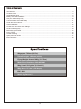
Table of Contents Introductions ··························································································································3 Contents of Kit ························································································································4 Assemble the plane ·················································································································5 Battery and radio installation ·····················································
Contents of Kit Before assembly, please inspect the contents of the kit. The photo below details the contents of the kit and labels. If any parts are missing or defective, please indentify the name or part number (refer to the spare parts list near the end of the manual) then contact your local shop or email us: support@fmsmodel.com A. B. F. E. H. D. C. I. G. J. : Bomb : Spinner : Air Speed Head : Missile Set : Screws (HKM3.0x10*4;PA2.
Horizontal Tail Installation 1. Glue the air speed head on the nose cone. Ensure the air speed head and nose cone are in perfect alignment (fig1). Required Adhesives: Medium CA fig1 2. Apply the nose cone to the front fuselage as diagram shows. Ensure the nose cone is on the correct side (fig2). fig2 fig2 3. Install the fins into place with glue, the higher side towards the front of the plane (fig3). Note: the fin will angle towards the outboard of the plane as picture shows (fig4).
4. The bottom of the fuselage faces up. Carefully apply CA to the base and side of the rear fuselage slot. Install the stabilizer into place. Ensure the control horn is face up as shown (fig5). Note: Ensure the stabilizer horizontal axis is parallel to the wing as shown (fig6). Adjust any misalignment before the glue dries thoroughly. Required Adhesives: Medium CA fig5 fig6 fig6 5. Carefully apply CA to the top rear fuselage slot. Install the vertical stabilizer into place.
6. Install the wing 1. Slide the wing tube into the fuselage (fig8). 2. Install the left and right wing over the wing tube and into the wing slot of the fuselage (fig9). 3. Secure the left and right wings to the fuselage using the included 4 screws (fig10). fig8 fig9 HKM3.
7. Install the front and main landing gear with the included screws (fig11/fig12). PA 2.0x8 Hex screws 4x5 fig11 fig12 8. Correctly mount the wing tip missiles with glue. The missiles are correctly mounted when the top of the missiles are level with the surface of the main wing (fig13/fig14). fig13 fig14 9. Install the clevis. Refer to the Clevis Installation on page 12.
Battery and radio installation 1 2 16 fig16 fig16 fig17 9
Get your model ready to fly Important ESC and model information 1. The ESC included with the model has a safe start. If the motor battery is connected to the ESC and the throttle stick is not in the low throttle or off position, the motor will not start until the throttle stick is moved to the low throttle or off position. Once the throttle stick is moved to the low throttle or off position, the motor will emit a series of beeps.
The transmitter and model setup Before getting started, bind your receiver with your transmitter. Please refer to your Transmitter Manual for proper operation CAUTION: To prevent personal injury, DO NOT install the propeller assembly onto the motor shaft while testing the control surfaces. DO NOT arm the ESC and do not turn on the transmitter until the Transmitter Manual instructs you to do so.
Clevis Installation a. Pull the tube from the clevis to the linkage. b. Carefully spread the clevis, then insert the clevis pin into the desired hole in the control horn. c. Move the tube to hold the clevis on the control horn. a. d. b. e. c. f. Control Horn and Servo Arm Settings The table shows the factory settings for the control horns and servo arms. Fly the aircraft at the factory settings before making changes.
Check the C.G. (Center of Gravity) When balancing your model, adjust the motor battery as necessary so the model is level or slightly nose down. This is the correct balance point for your model. After the first flights, the CG position can be adjusted for your personal preference. 1. The recommended Center of Gravity (CG) location for your model is (90-95mm) forward from the leading edge of the main wing (as shown) with the battery pack installed. Mark the location of the CG on top of the wing. 2.
Before flying the model Find a suitable flying site Find a flying site clear of buildings, trees, power lines and other obstructions. Until you know how much area will be required and have mastered flying your plane in confined spaces, choose a site which is at least the size of two to three football fields - a flying field specifically for R/C planes is best. Never fly near people especially children, who can wander unpredictably.
Flying course Take off While applying power, slowly steer to keep the model straight. The model should accelerate quickly. As the model gains flight speed you will want to climb at a steady and even rate. F-16 will climb out at a nice angle of attack (AOA). Flying Always choose a wide-open space for flying your plane. It is ideal for you to fly at a sanctioned flying field. If you are not flying at an approved site always avoid flying near houses, trees, wires and buildings.
Troubleshooting 16
Spare parts list content ROCKN101 ROCKN102 ROCKN103 ROCKN104 ROCKN105 ROCKN106 ROCKN107 ROCKN108 ROCKN109 ROCKN110 ROCKN111 ROCKN112 ROCKN113 FMS64MM11B FMSKV3900E PRESC001 FMSSER9GP FMSSER9GR FMSSER9G54 FMSPilot014 Fuselage Main Wing Set Horizontal Stabilizer Vertical Stabilizer Nose Cone Canopy Ventral Fin Fuel Tanks Missile A Missile B Linkage Rod Landing Gear Set Air Speed Head 64mm Ducted Fan KV3900 Motor (2840-KV3900 motor) 40A ESC 9g Servo Positive 9g Servo Reverse 9g Servo 54 Degree Pilot Visit ou
ESC instruction 18