
Datasheet


flexible enough to allow additional
commands.
• Repeatedly sending the volume
adjustment commands if the corresponding
switches are held down, so that the volume
continues to increase or decrease, as
required.
• Making sure that data is transmitted at
the correct rate for the Archos to recognize
it. The specification of the ’508A’s internal
oscillator timing is not quite as accurate as
required for serial communications.
In the following section, I’ll cover each
of these points in turn. Where appropriate,
I’ll refer to excerpts of the code included in
the article, but you may find it useful to
have the complete code listing (available
from the Nuts & Volts FTP library at
www.nutsvolts.com) on hand.
Also, if you’re not familiar with the
’508A’s assembly language, it is worth
getting the datasheet from Microchip (w w w.micro
chip.com).
While there’s not enough room in this article to
discuss the entire code listing, I believe that — armed with
the datasheet, the code listing, and the following description
— you’ll soon understand how the remote works.
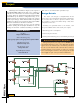
Driving the Archos
The Archos expects an open-drain driver for serial data.
Unfortunately, the ’508A does not have an open-drain out-
put. To overcome this limitation, I implemented one by
using the PIC’s ability to tri-state its output pins.
When the data line is idle, it needs to be at logic 1,
which for the Archos recorder is 3.3 V. By tri-stating
(disabling) GP2 using the TRIS register, a pullup in the
recorder drives the data line to 3.3 V. To put a 0 into the
data line, GPIO bit 2 must be set to 0 and then the TRIS
register must be set to enable GP2.
Impor t ant: Be sure to read the information in
the sidebar before making any changes to the code,
particularly if you build the remote with a 5 V PIC.
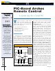
PIC-Based Archos Remote
MAY 2004
47
************************************************************************
‘Now we check the button status and repeat this loop until there has
been no change in button state for 10 ms.
‘
‘NOTE: The timing of this loop is important, since it is used as the
basis for debounce timing. Be careful when modifying the path taken
when the buttons haven’t changed — DEBCNT will need to be modified.
************************************************************************
dbncloop
call readbtns ; [35] Read the button status.
movf btnstat,w ‘[36] Get current button state.
subwf buttons,f ‘[37] Compare with last reading
movwf buttons ‘[38] Save new value. We only need Z flag
btfsc STATUS,Z ; [39] Have they changed?
goto nobtnchg ; [41] NO: Need to see if debounced.
movlw DEBCNT ‘YES: Start debounce timer again.
movwf dbnctmr
movlw RPTDLY ‘Set repeat delay.
movwf rptdelay
goto dbncloop ; ...and go back to read buttons again.
‘Buttons didn’t change this time around; decrement timer.
nobtnchg
decfsz dbnctmr,f ; [42] Decrement debounce timer; test if done.
goto dbncloop ; [44] NO: Go back and read buttons again.
Example 1
Circle #105 on the Reader Service Card.