
Datasheet


Power Consumption
To keep power consumption to a minimum — thereby
extending battery life — the design ensures that the ’508A
spends most of its time asleep, drawing almost no current
(about 2 or 3 µA). The MCU’s Option register is set to
wake the device up on a pin state change, so that it
responds when the user presses one or more of the
switches. Other features set in the Option register enable
the weak pullup resistors on GP0, 1, and 3 and assign the
MCU’s pre/post-scaler to the watchdog
timer (WDT).
When the user presses a switch,
the ’508A wakes up and, after
debouncing the switch, sends the
appropriate command to the recorder
before going back to sleep. The WDT is
a counter that runs even when the PIC
is asleep. When it reaches its terminal
count, it wakes the PIC up. In many
designs, the WDT is used to reset the
MCU if something interferes with the
correct operation of the program. For
the remote, however, it is primarily
used to wake the PIC up when the
user is holding one of the volume
adjustment switches down. This allows
the remote to send multiple commands
without the user having to press the
same switch repeatedly.
When another switch or no switch
is held down, the WDT period is set to
its maximum (nominally 2.3 s), since it
cannot be completely disabled. By
calculating the current drawn by the
remote in its various modes and
making assumptions about how often
the user will press switches, it is
possible to calculate its average power
consumption. I assumed that the user would make an
average of two key presses for every three minute song
for eight hours a day. This gives an average current of
about 12 µA, which means that a 200 µA CR2032 cell
should last for about 700 days — nearly two years.
Handling Key Presses
Mechanical switches usually “bounce” when they
change state. This means that, rather than changing
directly from OFF to ON, they oscillate between OFF and
ON for a short time (several milliseconds, typically)
before stabilizing in the new state. For a light switch, this
isn’t really a problem, but, for electronic equipment, the
oscillation can be seen as several distinct switch presses
instead of just one. If this occurred for a press of the Next
switch on the remote, for example, the recorder would
skip perhaps four or five songs rather than just moving to
the next one to be played.
To “debounce” the switches when the PIC wakes up
due to a pin change, it reads the switches multiple times
and waits until there has been no change for about 10 ms
(set by DEBCNT). If the switches change before the 10
ms has expired, the debounce timer is started again. The
debounce loop is shown in Example 1.
By the way, if you take a look at the routine that reads
the switch status (readbtns), you’ll see a string of nop
MAY 2004
48
N
UTS &
V
OLTS
Everything For Electronics
Project
***************************************************************************
‘bitdelay
‘
‘ INPUT: The value in bitadjust is initialized at POR to make the
entire loop starting at nextbit in xmit take exactly 104 instruction
clocks. Increasing or decreasing bitadjust by 1 adds or subtracts 1 clock,
respectively, to the serial data bit time.
‘ OUTPUT: None
‘
***************************************************************************
bitdelay
movf bitadjust,w ‘Get the necessary adjustment
movwf loopcnt ‘Save it in the delay loop counter
bcf STATUS,C ‘ but divide by 4 (loop length)
rrf loopcnt,f
bcf STATUS,C
rrf loopcnt,f
movlw 0x03 ‘Get mask for low two bits
andwf bitadjust,w ‘ ...and isolate them
xorlw 0x03 ‘ Invert them (0->3, 1->2, 2->1, 3->0)
addwf PCL,f ‘ Use the number to trim the cycle count.
nop
nop
nop
bit1
nop ‘This loop is four clocks in length; use
decfsz loopcnt,f calculated value to generate bit timing.
goto bit1
nop ‘Last time through loop has to be four
clocks, too.
retlw 0
Example 2
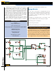
Figure 4.
Printed circuit.