
Datasheet


via a link in fntable.
Calibration Mode
Asynchronous communication depends on both
transmitter and receiver running at the same speed. The
recorder expects 9,600 bits per second, which equates to
about 104 µs per bit. Since each instruction takes 1 µs to
execute, the subroutine that sends commands to the
recorder (xmit) sends the start bit and then it must take
exactly 104 instructions before sending each successive
bit. The xmit routine uses some of these 104 instructions
up, but calls bitdelay to pad the count out to 104.
It can be shown that the accuracy of the MCU clock
must be better than ±7.7% to ensure accurate reception of
the command by the recorder. The figure for eight-bit
commands is actually ±5.8%, but, as the top two bits
and the stop bit are all logic 1, the less accurate figure is
sufficient. Microchip make the internal clock as accurate
as it can (again, see the sidebar), but, even so, the
specification for the ’508A’s clock is +7.75%, -11.25%
from 0-70°C. Therefore, calibrate mode allows the user to
modify the bit period by ±16 clock cycles (about ±15%) to
compensate for the widest deviations from nominal.
Pressing Next or Previous in Calibrate mode decreases
or increases (respectively) the transmit bit time by one
instruction cycle by modifying the value of bitadjust.
Because a loop takes a minimum of three instructions, I
used an nop instruction to make the loop four clocks long.
This allowed me to use the two low order bits to calculate
a small jump to add the required extra zero to three clocks.
Take a look at Example 2 to see how this works.
While in calibrate mode, a series of Volume Down and
Volume Up commands is transmitted so that it is easy to
see when the recorder is receiving commands. If the
timing is not accurate enough, the commands are
ignored. From limited testing, it appears that calibration
will not be necessary in most cases, but it is there if it is
needed. Full instructions for calibration mode are given in
the description near the top of the full code listing.
Switch presses in calibrate mode are handled
through another jump table, called calt able. Any
additional functions that may be required can be easily
incorporated via a link in caltable.
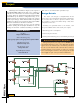
Completing the Project
The remote uses few components, so construction is
Project
MAY 2004
50
N
UTS &
V
OLTS
Everything For Electronics
Tools for Construction
Construction is straightforward — just make sure you
get the ’508A situated the right way.The ceramic capacitors I
used were not polarized.Take care in soldering the PIC pins in
particular to make sure that no solder bridges are formed.
Note that you will need a device programmer to program
the PIC12C508A. A quick Google search found many sites
from which you can purchase relatively cheap programmers
and programmer kits (under $100.00 and some for much
less).
Tools for Debug
A multimeter is handy for checking voltages. It is useful to
have access to an oscilloscope to make sure the serial data is
being transmitted before you actually connect the remote to
your recorder. Because GP2 is acting as an open drain output,
you’ll need to connect a resistor between GP2 and the
positive side of the battery to see the data.The resistor value
is not critical — 1K to 10K will be fine. Remember to remove
it afterward!
If you don’t have access to a ’scope, check that there’s no
significant voltage on the serial data pole of the jack plug and
that a resistor pulls it to the battery voltage before trying it
on your recorder.
You should also test that the left and right audio paths are
working correctly.You can do this easily by connecting some
headphones to the remote and briefly connecting a 1.5V AA
or AAA battery between the left and right audios and grounds
on the four pole jack plug.You should hear clicks only in the
selected channel.
As long as you have not made any assembly errors, you’ll
plug the remote into your recorder and, with a little luck, it
will work. If not, you’ll need to attempt to calibrate the device
as described. If calibration doesn’t resolve the problem, check
all of your connections and you may find that an oscilloscope
is really necessary to complete the debug.
Tools
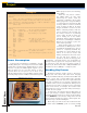
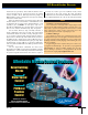
Figure 5.
The completed remote control.
Information required to drive the remote port of
Archos devices was gleaned from Tjerk Schuringa, author of
the original REMOCLONE remote software (implemented
with a 16LF84) and the authors of Rockbox — the amazing
open source alternative to the Archos’ proprietary firmware.
Acknowledgements