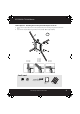
RF-TVMP40_13-0238_MAN_V1_ENG.fm Page 1 Monday, April 15, 2013 1:26 PM RF-TVMP40 TV Wall Mount For wood-stud and concrete wall installations Safety information and specifications .................................2 Tools needed.................................................................................2 Package contents: parts ............................................................3 Package contents: hardware ...................................................4 Installation instructions..........
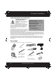
RF-TVMP40_13-0238_MAN_V1_ENG.fm Page 2 Monday, April 15, 2013 1:26 PM RF-TVMP40 TV Wall Mount Safety information and specifications IMPORTANT SAFETY INSTRUCTIONS SAVE THESE INSTRUCTIONS Maximum TV weight: 40 lbs. (18.1 kg) CAUTION: Do not use this product for Minimum TV weight: 18 lbs. (8.2 kg) any purpose not explicitly specified by Maximum TV Screen size: 55 in. diagonal Rocketfish. Overall dimensions (W × H ): Improper installation may cause property damage or personal injury. If 3.5 x 8.9 in. (9.
RF-TVMP40_13-0238_MAN_V1_ENG.
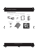
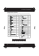
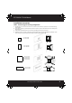
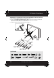
RF-TVMP40_13-0238_MAN_V1_ENG.fm Page 4 Monday, April 15, 2013 1:26 PM RF-TVMP40 TV Wall Mount Package contents: hardware Make sure that you have all the hardware necessary to assemble your new TV wall mount: TV Hardware Bag Label M-A Hardware Qty.
RF-TVMP40_13-0238_MAN_V1_ENG.fm Page 5 Monday, April 15, 2013 1:26 PM RF-TVMP40 TV Wall Mount Installation instructions STEP 1 - Determining your mounting configuration 1 2 3 4 Carefully place your TV screen face down on a cushioned, clean surface to protect the screen from damage and scratches. If your TV has a table top stand attached, remove the stand. See the documentation that came with your TV for instructions. Temporarily hold the flat surface of the monitor plate (C) against the back of your TV.
RF-TVMP40_13-0238_MAN_V1_ENG.fm Page 6 Monday, April 15, 2013 1:26 PM RF-TVMP40 TV Wall Mount STEP 2 - Determine whether your TV has a flat back or an irregular or obstructed back 1 With the monitor plate (C) and spider adapters (F) still on your TV, identify which type of back your TV may have: • Flat back: The monitor plate and adapters (if necessary) lay flush against the back of your TV and do not block any jacks. You do not need spacers when assembling the wall mount.
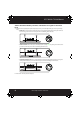
RF-TVMP40_13-0238_MAN_V1_ENG.fm Page 7 Monday, April 15, 2013 1:26 PM RF-TVMP40 TV Wall Mount STEP 3 - Select screws, washers, and spacers 1 Select the screws for your TV. A limited number of TVs come with mounting hardware included. (If there are screws that came with the TV, they are usually in the holes on the back of the TV.) If you don't know the correct length and diameter of the mounting screws your TV requires, test various sizes by hand threading the screws.
RF-TVMP40_13-0238_MAN_V1_ENG.fm Page 8 Monday, April 15, 2013 1:26 PM RF-TVMP40 TV Wall Mount STEP 4: Option 1 - Attaching the monitor plate to the TV 1 2 Align the monitor plate (C) with the screw holes on the back of the TV. Install screws (M-A, M-B, M-C, M-D, M-E, M-F, M-G, or M-H) securely into the four holes in the back of the TV, using washers (M-K or M-L) and spacers (M-I or M-J) as necessary. Do not over-tighten. Continue to “STEP 5 - Determine wall-mount location” on page 11.
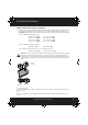
RF-TVMP40_13-0238_MAN_V1_ENG.fm Page 9 Monday, April 15, 2013 1:26 PM RF-TVMP40 TV Wall Mount STEP 4: Option 2 - Attaching the monitor plate with adapters to the TV 1 2 Position the four adapters (F) onto the monitor plate (C) to fit your TV mounting configuration determined in Step 1. Secure the four adapters (F) by using four M5 x 7 mm screws (P - B) and eight nuts (P-C).
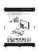
RF-TVMP40_13-0238_MAN_V1_ENG.fm Page 10 Monday, April 15, 2013 1:26 PM RF-TVMP40 TV Wall Mount STEP 4: Option 2 - Attaching the monitor plate with adapters to the TV (continued) 3 4 Align the adapters (F) with the screw holes on the back of your TV. Install screws (M-A, M-B, M-C, M-D, M-E, M-F, M-G, or M-H) securely into the four holes in the back of the TV, using washers (M-K or M-L) and spacers (M-I or M-J) as necessary. Do not over-tighten.
RF-TVMP40_13-0238_MAN_V1_ENG.fm Page 11 Monday, April 15, 2013 1:26 PM RF-TVMP40 TV Wall Mount STEP 5 - Determine wall-mount location Choose the TV location with the arm stowed and extended. Note that the TV will move side-to-side when pushing it into and pulling it out from the wall as well as lifting it up and lowering it down. This step requires an understanding of this products Range of Motion (see section RANGE OF MOTION on page 12).
RF-TVMP40_13-0238_MAN_V1_ENG.fm Page 12 Monday, April 15, 2013 1:26 PM RF-TVMP40 TV Wall Mount Mounting considerations: top top front •Wall Mount Bracket MUST be attached to a stud or solid concrete. DO NOT attach this product to hollow wall or any other configuration. •Make sure that the arm will have desired unobstructed range of motion: up-down, side-to-side, in-out (see RANGE OF MOTION). •Make sure cables will reach their destinations with enough remaining slack to allow Arm full range of motion.
RF-TVMP40_13-0238_MAN_V1_ENG.fm Page 13 Monday, April 15, 2013 1:26 PM RF-TVMP40 TV Wall Mount STEP 6 - Option 1: Installing on a wood stud wall Note: Any wallboard or material covering the wall must not exceed 5/8" (16 mm). 1 2 3 4 Locate the stud. Verify the center of the stud with an edge-to-edge stud finder. Align the wall plate template (G) at the height you determined in the previous step and make sure that it is level, then tape it to the wall.
RF-TVMP40_13-0238_MAN_V1_ENG.fm Page 14 Monday, April 15, 2013 1:26 PM RF-TVMP40 TV Wall Mount STEP 6 - Option 2: Installing on a solid concrete wall 1 2 3 4 Align the wall plate template (G) at the height you determined in the previous step and make sure that it is level, then tape it to the wall. Use a pencil to mark the lag bolt hole locations (2). Remove the template. Drill pilot holes to a depth of 2-3/4 in. (7 mm) using a 3/8 in. (10 mm) diameter masonry drill bit.
RF-TVMP40_13-0238_MAN_V1_ENG.fm Page 15 Monday, April 15, 2013 1:26 PM RF-TVMP40 TV Wall Mount STEP 7 - Attach the arm assembly to the wall plate 1 2 3 4 Install the top and bottom covers (E) onto the wall plate (D). Place the tubing (P-M) into the hole in the top of the wall plate (D), then place the 65mm washer (P-F) over the tubing (P-M).
RF-TVMP40_13-0238_MAN_V1_ENG.fm Page 16 Monday, April 15, 2013 1:26 PM RF-TVMP40 TV Wall Mount STEP 8 - Attach your TV to the arm assembly 1 2 Holding the TV level, with the screen parallel to the wall, connect the monitor plate (C) to the arm assembly (A), as shown below. Secure with the phillips screw (P-A) through the arm assembly (A) into the monitor plate (C) and tighten the screw. A C HEAVY! You will need assistance with this step.
RF-TVMP40_13-0238_MAN_V1_ENG.fm Page 17 Monday, April 15, 2013 1:26 PM RF-TVMP40 TV Wall Mount STEP 9 - Installing the cable wrap and cable ties 1 2 Connect the cable to your TV, then secure the cable to the underside of the arm assembly (A) with two cable ties (P-L). Install the cable wrap (P-D) on the cables to provide a neater appearance.
RF-TVMP40_13-0238_MAN_V1_ENG.fm Page 18 Monday, April 15, 2013 1:26 PM RF-TVMP40 TV Wall Mount STEP 10 - Adjusting the vertical motion Important! You will need to adjust this product after installation is complete. Make sure all your equipment is properly installed on the product before adjusting. This product should move smoothly and easily through the full range of motion and stay where you set it.
RF-TVMP40_13-0238_MAN_V1_ENG.fm Page 19 Monday, April 15, 2013 1:26 PM RF-TVMP40 TV Wall Mount STEP 11 - Adjusting the setting for pan tension 1 2 3 Remove the bolt cover from the adjustment bolt. To increase or decrease the pan tension, use a 1/2” (13 mm) socket wrench. Replace the bolt cover to the adjustment bolt. Adjusting the factory-set tension Increase If your TV moves too easily from side to side, increase the tension.
RF-TVMP40_13-0238_MAN_V1_ENG.fm Page 20 Monday, April 15, 2013 1:26 PM RF-TVMP40 TV Wall Mount STEP 12 - Adjusting the horizontal movement 1 2 3 Lift the arm assembly up to it’s highest point, then remove the rear arm cover (B). To increase or decrease horizontal movement tension, us a 1/2” (13 mm) socket wrench. Replace the rear arm cover. Adjusting the factory-set tension Increase If your TV moves too easily from side to side, increase the friction.
RF-TVMP40_13-0238_MAN_V1_ENG.fm Page 21 Monday, April 15, 2013 1:26 PM RF-TVMP40 TV Wall Mount STEP 13 - Adjusting the tilt • To increase or decrease the tilt tension, turn the adjustment knob on the side of the arm assembly. Adjusting the factory-set tension Increase If TV weight exceeds product’s factory setting, it won’t stay up when raised. To prevent TV from sagging downward, increase tension setting. Decrease If TV weight is lower than product’s factory setting, it won’t stay down when lowered.
RF-TVMP40_13-0238_MAN_V1_ENG.fm Page 24 Monday, April 15, 2013 1:26 PM www.rocketfishproducts.com (800) 620-2790 Distributed by Best Buy Purchasing, LLC 7601 Penn Avenue South, Richfield, MN 55423-3645 USA © 2013 BBY Solutions, Inc. All rights reserved. ROCKETFISH is a trademark of BBY Solutions, Inc. All other products and brand names are trademarks of their respective owners.