Power Power Power Power Power Power Power Power 250 2-Channel 360 2-Channel 400 4-Channel 500 2-Channel 600 5-Channel 800 2-Channel 800 4-Channel 1000 2-Channel Power Amplifier Páginas de Referencia para la Instalación Schéma d’Installation Installations Beiblatt Istruzioni di Installation Installation and Operation
GETTING STARTED Welcome to Rockford Fosgate! This manual is designed to provide information for the owner, salesperson and installer. For those of you who want quick information on how to install this product, please turn to the Installation Section of this manual or refer to the icons listed below. Other information can be located by using the Table of Contents. We, at Rockford Fosgate, have worked very hard to make sure all the information in this manual is current.
Dear Customer, Congratulations on your purchase of the world's finest brand of car audio amplifiers. At Rockford Fosgate we are fanatics about musical reproduction at its best, and we are pleased you chose our product. Through years of engineering expertise, hand craftsmanship and critical testing procedures, we have created a wide range of products that reproduce music with all the clarity and richness you deserve.
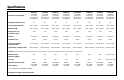
Specifications POWER 250 2-channel POWER 360 2-channel POWER 400 4-channel POWER 500 2-channel POWER 600.
Specifications Dimensions (end caps installed) POWER 250 2-channel 2.4" (6.1cm) H 9.9" (25.06cm) W 11.4" (28.88cm) L POWER 360 2-channel 2.4" (6.1cm) H 9.9" (25.06cm) W 12.4" (31.42cm) L POWER 400 4-channel 2.4" (6.1cm) H 9.9" (25.06cm) W 13.4" (33.96cm) L POWER 500 2-channel 2.4" (6.1cm) H 9.9" (25.06cm) W 13.4" (33.96cm) L POWER 600.5 5-channel 2.4" (6.1cm) H 9.9" (25.06cm) W 18.4" (46.74cm) L POWER 800 2-channel 2.4" (6.1cm) H 9.9" (25.06cm) W 18.4" (46.74cm) L POWER 800 4-channel 2.4" (6.
Table of Contents Specifications.............................................................................................. i Introduction ................................................................................................1 Power Amplifier Accessory Pack ....................................................................1 Feature Chart ..............................................................................................2 Design Features .............................................
Introduction Rockford engineers designed the Power series amplifiers to withstand the rugged automotive environment while delivering superior sound quality in a flexible, reliable, and efficient package. TRANS•ana is a low voltage circuit in the preamp stage lets the music sound crystal clear and very real, even when played at high volume levels. This is matched with TOPAZ, a unique grounding circuit used to eliminate noise problems associated with car audio systems and their installation.
Power Amplifier Feature Chart POWER AMPLIFIER MODEL –2– # of CHANNELS Stable Into: (stereo/mono) CIRCUITRY1 TRANS•ana – circuit topology TRANS•nova – patented circuit topology2 DIAMOND – patented MOSFET driver stage3 Class-G – high efficiency topology MEHSA – heat dissipating technology TOPAZ – patented noise eliminating circuitry4 DSM – discrete surface mount MOSFETs – power supply & output devices NOMAD – protection circuit FEATURES Die Cast Heatsink Hi-Level Inputs – for factory radios RCA Inputs – for
Design Features 1. Cast Aluminum Heatsink – The cast aluminum heatsink of the Power amplifier dissipates heat generated by the amplifier's circuitry. The inherent advantage of casting provides a 30% improvement of cooling over conventional extrusion heatsink designs. 2. Speaker/Power Terminals – The heavy duty, gold-plated terminal block connectors (+ and –) will accept 4 gauge cable and are immune to corrosion that can cause signal degradation. 3.
Power 250 2-channel 2 9 7 5 7 8 7 8 9 2 1 6 3 10 2 Power 360 2-channel 2 9 7 5 210 Hz 50 190 55 145 110 65 80 L Speaker + L - R L Pass-Thru R 6 3 10 REM B+ 2 HP-Full-LP Crossover Input Left Gain Crossover Frequency 9 GND 2 –4– Right Remote Gain Punch Bass Speaker + R - 1
Power 400 4-channel 7 9 4 Front Crossover HP-Full-LP 4/2 Input Front Gain 9 9 5 210 Hz 50 190 55 145 110 65 80 R Front Crossover Frequency 210 Hz 50 190 55 145 110 65 80 R L Pass-Thru 8 Rear Crossover HP-Full-LP Rear Rear Gain Crossover Frequency L Front 9 7 1 Rear Remote Punch Bass Rear 6 2 LR+ LR- 3 RR+ RR- 2 10 B+ REM GND LED LF- LF+ RF- RF+ 2 Power 500 2-channel 2 9 7 7 5 210 Hz 50 190 55 145 110 65 Left 80 L Speaker + L - R L Pass-Thru R 6 3 10 R
Power 600 5-channel 9 Sub LP Sub Crossover Punch Frequency Bass 210 Hz 50 190 55 145 110 65 80 4 5 Sub Gain 9 8 R R L L 10 Rear Rear Crossover Punch Rear Gain Remote Frequency Bass Punch Bass HP-Full-LP Rear Crossover 6/4/2 Input Sub Rear Front 10 7 2 RR+ LR- RF- LF+ Sub- RR- LR+ RF+ LF- Sub+ 3 9 9 Front Front Crossover Punch Frequency Bass 210 Hz 50 190 55 145 110 65 80 Front Gain HP-Full-LP Front Crossover 2 7 1 7 REM RR+ LR- RF- LF+ Sub- RR- LR+ RF+ LF-
Power 800 4-channel 9 4 Front Crossover HP-Full-LP 4/2 Input 7 Front Gain 9 9 5 210 Hz 50 190 55 145 110 65 80 R Front Crossover Frequency Front 210 Hz 50 190 55 145 110 65 80 R L 7 Rear Rear Gain Crossover Frequency L Pass-Thru 9 8 Rear Crossover HP-Full-LP 1 Rear Remote Punch Bass Rear 6 3 2 2 10 REM LR+ LR- RR+ RR- B+ GND LF- LF+ RF- RF+ 2 Power 1000 2-channel 2 11 9 7 7 5 Input Speaker + L - Phase Crossover Left Warp Frequency Gain L 210 Hz 50 190 55 1
Installation Considerations This is a list of tools you will need for installing the Power amplifier: • • • • • Voltmeter Electric hand drill w/assorted bits 17' (5 m) Red Power Wire 12' (4 m) Remote Turn-On Wire 1.5' (45 cm) Black Grounding Wire • Wire strippers • Battery post wrench • Wire cutters • Assorted connectors • Wire crimpers This section focuses on some of the vehicle considerations for installing your new Power amplifier.
Mounting Location The mounting location and position of your amplifier will have a great effect on its ability to dissipate the heat generated during normal operation. The design of our cast aluminum heatsink serves to easily dissipate the heat generated over a wide range of operating conditions. However, to maximize the performance of your amplifier, care should be taken to ensure adequate ventilation.
Battery and Charging Amplifiers will put an increased load on the vehicle's battery and charging system. We recommend checking your alternator and battery condition to ensure that the electrical system has enough capacity to handle the increased load of your stereo system. Stock electrical systems which are in good condition should be able to handle the extra load of any Rockford amplifier without problems, although battery and alternator life can be reduced slightly.
4. Prepare a length of cable to be used for the ground connection. Strip 5/8" of insulation from the end of the cable as described above and connect to the appropriate terminal of the amplifier. Prepare the chassis ground by scraping any paint from the metal surface and thoroughly clean the area of all dirt and grease. Strip the other end of the wire and attach a ring connector. Fasten the cable to the chassis using a nonanodized screw and a star washer. 5.
Using Passive Crossovers +- I N S T A L L A T I O N A passive crossover is a circuit that uses capacitors and/or coils and is placed on speaker leads between the amplifier and speaker. The crossover delegates a specific range of frequencies to the speaker for optimum driver performance. A crossover network can perform one of three functions: High-Pass (capacitors), Low-Pass (inductors or coils) and Bandpass (combination of capacitor and coil).
Table of Crossover Component Values L C 6dB/Octave High-Pass 6dB/Octave Low-Pass Speaker Impedance Freq. Hertz 2 OHMS 8 OHMS 4 OHMS C L C L L C 80 100 130 4.1mH 3.1mH 2.4mH 1000µF 800µF 600µF 8.2mH 6.2mH 4.7mH 500µF 400µF 300µF 16mH 12mH 10mH 250µF 200µF 150µF 200 260 400 1.6mH 1.2mH .8mH 400µF 300µF 200µF 3.3mH 2.4mH 1.6mH 200µF 150µF 100µF 6.8mH 4.7mH 3.3mH 100µF 75µF 50µF 600 800 1000 .5mH .41mH .31mH 136µF 100µF 78µF 1.0mH .82mH .62mH 68µF 50µF 39µF 2.0mH 1.6mH 1.
Installation +- Power 250 2-channel Power 360 2-channel Power 500 2-channel Power 800 2-channel I N S T A L L A T I O N Power 250 Power 360 Power 500 Power 800 Power Connections 2-channel 2-channel 2-channel 2-channel LED REM B+ GND Connect to remote turn-on lead of source unit Connect to chassis ground of vehicle* Less than 18" + - Connect to B+ of battery with appropriate fuse *Keep grounds as short as possible Bridged/Mono Mode Power 250 Power 360 Power 500 Power 800 2-channel 2-c
+- 2-Channel Mode Power 250 Power 360 Power 500 Power 800 2-channel 2-channel 2-channel 2-channel RCA Input 210 Hz 50 190 55 145 110 65 HP-Full-LP Crossover Input Left Gain 80 Crossover Frequency L Speaker + L - R Right Remote Gain Punch Bass Speaker + R - L Pass-Thru R – – 2Ω min. 2Ω min.
Installation +- Power 400 4-channel Power 800 4-channel Power Connections Power 400 Power 800 4 -channel 4 -channel LED REM B+ GND Connect to remote turn-on lead of source unit Connect to chassis ground of vehicle* Less than 18" + - Connect to B+ of battery with appropriate fuse *Keep grounds as short as possible – 16 – I N S T A L L A T I O N
+- 2-Channel Mode Power 400 Power 800 4 -channel 4 -channel RCA Input 4-2 Input 4/2 Input Front Gain 210 Hz 50 190 55 145 110 65 80 Front Crossover Frequency Front R R L L Pass-Thru 210 Hz 50 190 55 145 110 65 80 LR- RR+ LED B+ GND - 4Ω min. Bridged Left • • • • • LF- LF+ RF- - + RR- Rear Remote Punch Bass Rear REM LR+ Rear Crossover HP-Full-LP Rear Rear Gain Crossover Frequency RF+ + Front Crossover HP-Full-LP 4Ω min.
+- 3-Channel Mode Power 400 Power 800 4-channel Input 4-channel 4-channel 2-channel Input 4-2 Input -or- Front Crossover HP-Full-LP 4-2 Input 4/2 Input Front Gain 210 Hz 50 190 55 145 110 65 80 Front Crossover Frequency Front R R L L Pass-Thru 210 Hz 50 190 55 145 110 65 80 Rear Rear Gain Crossover Frequency Rear Crossover HP-Full-LP Rear Remote Punch Bass Rear REM RR+ RR- B+ GND LF- LF+ RF- + LR- - LR+ RF+ * + - - • • • • • • + 2Ω min. 4Ω min. Bridged 2Ω min.
+- 4-Channel Mode Power 400 Power 800 4-channel 4-channel 4-channel Input 4-2 Input Front Crossover HP-Full-LP 4/2 Input Front Gain 210 Hz 50 190 55 145 110 65 80 Front Crossover Frequency Front R R L L Pass-Thru 210 Hz 50 190 55 145 110 65 80 Rear Rear Gain Crossover Frequency Rear Crossover HP-Full-LP Rear Remote Punch Bass Rear REM + 2Ω min. • • • • • B+ GND - LF- - - + RR- 2Ω min. 2Ω min. LF+ RF- + RR+ - LR- RF+ + LR+ 2Ω min.
+- Power 600 5-Channel Mode 5-channel 6-channel input 6/4/2 Input Sub LP Sub Crossover Punch Frequency Bass 210 Hz 50 190 55 145 110 65 80 R Sub Gain R Rear Rear Crossover Punch Remote Frequency Bass Punch Bass L Rear Gain HP-Full-LP Rear Crossover 6/4/2 Input Sub Rear RR+ LR- RF- LF+ Sub- RR- LR+ RF+ LF- Sub+ Front Front Front Crossover Punch Frequency Bass 210 Hz 50 190 55 145 110 65 80 Front Gain HP-Full-LP Front Crossover REM LR- RF- LF+ Sub- RR- LR+ RF+ LF- Sub+ B+
Installation +- Power 1000 2-channel Power 1000 Power Connections 2 -channel REM B+ GND Connect to remote turn-on lead of source unit Connect to chassis ground of vehicle* Less than 18" + - Connect to B+ of battery with appropriate fuse *Keep grounds as short as possible Power 1000 Bridged/Mono Mode 2 -channel RCA Input + - 4Ω min.
+- 2-Channel Mode Power 1000 2 -channel RCA Input Speaker + L - Speaker + R - – – 2Ω min. 2Ω min. + • • • • + RCA Inputs connect to both left and right channels Gain for left and right channels operate independently Speaker Impedance for each channel should be 2Ω minimum Variable Crossover can be set to High-Pass (HP), Low-Pass (LP) or Full Range (FULL) Power 1000 3-Channel Mode RCA Input 2 -channel Speaker + L - Speaker + R - – – 2Ω min. 2Ω min. + + + - 4Ω min.
Operation +- Crossover Operation All Models • HP Operation enables frequencies above the cut-off point to pass to the speaker • FULL Operation enables all frequencies to pass to the speaker • LP Operation enables frequencies below the cut-off point to pass to the speaker – 23 – I N S T A L L A T I O N
+- All Models Remote Punch Bass 210 Hz 50 190 55 145 110 65 L Speaker + L - 45Hz -0 67.5Hz Speaker + R - L Pass-Thru R Install Punch Bass in a convenient location under vehicle’s dash 33Hz 45Hz -0 +18 Minimum Flat Right Remote Gain Punch Bass R +18 +12 +6 +3 0dB 33Hz HP-Full-LP Crossover Input Left Gain 80 Crossover Frequency 67.5Hz +18 Maximum Boost • Carefully increase potentiometer to add Punch to your bass frequencies • Exercise caution when increasing Punch Bass.
+- Power 1000 Phase Warp 2-channel The Phase Warp is a variable control used to adjust the phase of the output signal relative to the phase of the input signal. This "phase alignment" is most noticable when used with an array of woofers whose vertical or horizontal planes are staggered (not eminating from the same point.) Adjusting the Phase Warp can electrically realign the signal fed to each woofer as if all woofers were aligned on a common ZDP.
System Diagrams 400 Watt 3-Way System BAND MUTE PUSH SEL VOL COMPACT DISC PLAYER WITH DIGITAL TUNER ST DISP LOCAL LOUD RPT CD CHANGER CONTROL RDM AS/PS MODE TRACK MENU SEEK LOUD SCAN RPT RDM 1 2 3 DISC 4 5 6 TUNE Rear Front Power 4-Channel Amplifier Fanatic Component System Punch Woofers – – + – + + – + 8Ω + – – + + – – + 8Ω 80Hz - 20kHz 24dB/octave HP 20Hz - 80Hz 24dB/octave LP – 26 –
650 Watt 4-Way System BAND MUTE PUSH COMPACT DISC PLAYER WITH DIGITAL TUNER SEL VOL ST DISP LOCAL LOUD RPT CD CHANGER CONTROL RDM AS/PS MODE LOUD TRACK SCAN RPT RDM 1 2 3 SEEK MENU DISC 4 5 6 TUNE Pass-Thru Rear Front Power 4-Channel Amplifier – 4Ω + + – – – – Fanatic Component System + 4Ω + – + + Punch Midbass + – 80Hz - 275Hz 12dB/octave LP 12dB/octave HP – + 275Hz - 20kHz 24dB/octave HP Punch Woofers + 8Ω + 8Ω Power 2-Channel Amplifier – – 20Hz
MUTE COMPACT DISC PLAYER WITH DIGITAL TUNER ST DISP LOCAL LOUD RPT CD CHANGER CONTROL RDM AS/PS MODE TRACK MENU 1050 Watt 4-Way System BAND PUSH SEL VOL LOUD SCAN RPT RDM 1 2 3 SEEK Front DISC 4 5 6 TUNE Rear Pass-Thru Power 4-Channel Amplifier Power 4-Channel Amplifier + – + – – + 80Hz - 275Hz 12dB/octave LP 12dB/octave HP + 275Hz - 20kHz 275Hz - 20kHz 24dB/octave HP 24dB/octave HP Punch Woofers + 8Ω 20Hz-80Hz 24dB/octave LP RFA-812 + 8Ω – – – + 80Hz - 27
MUTE COMPACT DISC PLAYER WITH DIGITAL TUNER ST DISP LOCAL LOUD RPT CD CHANGER CONTROL RDM AS/PS MODE LOUD TRACK MENU SEEK Front SCAN RPT RDM 1 2 3 DISC 4 5 6 TUNE Rear Pass-Thru Pass-Thru Power 4-Channel Amplifier Power 4-Channel Amplifier Fanatic Component System – + – – + + 275Hz - 20kHz 24dB/octave HP 80Hz - 275Hz + 20Hz-80Hz 24dB/octave LP + + 8Ω – 275Hz - 20kHz 24dB/octave HP Punch Woofers Punch Woofers 8Ω – 12dB/octave LP 12dB/octave HP + 80Hz - 27
Installation Troubleshooting TROUBLE S H O O T I N G If you are having problems after installation follow the Troubleshooting procedures below. Procedure 1: Check Amplifier for proper connections. Verify that POWER light is on. If POWER light is on skip to Step 2, if not continue. 1. Check in-line fuse on battery positive cable. Replace if necessary. 2. Verify that Ground connection is connected to clean metal of the vehicle’s chassis. Repair/replace if necessary. 3. Verify there is 10.5 - 15.
Installation Troubleshooting TROUBLE S H O O T I N G Procedure 4: Check Amplifier if you experience excess Engine Noise. 1. Route all signal carrying wires (RCA, Speaker cables) away from power and ground wires. OR 2. Bypass any and all electrical components between the stereo and the amplifier(s). Connect stereo directly to input of amplifier. If noise goes away the unit being bypassed is the cause of the noise. OR 3. Remove existing ground wires for all electrical components.
Dynamic Power Measurements About the Dynamic Power Measurements The Audio Graph PowerCube is a test instrument used to measure the output of an amplifier in accordance with IHF-202 industry standards. The IHF-202 standard is a dynamic power measurement and was developed as a means of measuring power in a manner that best represents the Real World operation of an amplifier. Many manufacturers, including Rockford Fosgate, at times will measure amplifier power into a fixed resistor (4 ohm, 2 ohm).
Information Cubed The data acquired in the testing procedure is then graphed in the form of a 3-dimensional cube, hence the name PowerCube. The Phase Angle is expressed on the horizontal axis, the Output Voltage is presented on the vertical axis and the Impedance is displayed on the Z axis. Output Power, in watts, is listed on the left hand side for each impedance at each phase angle. Audio Graph – The PowerCube™ x2 = STEREO MONO = BRIDGED MONO I M P E D A N C E Amplifier: PUNCH 200.2 14.
Limited Warranty Information Rockford Corporation offers a limited warranty on Rockford Fosgate products on the following terms: • Length of Warranty 3 years on electronics-90 days on electronic B-stock (receipt required) 1 years on source units 1 year on speakers-90 days on speaker B-stock (receipt required) • What is Covered This warranty applies only to Rockford Fosgate products sold to consumers by Authorized Rockford Fosgate Dealers in the United States of America or its possessions.
International Information ESPAÑOL LEA DETENIDAMENTE LAS SIGUIENTES INSTRUCCIONES DE INSTALACION DEL PRODUCTO. EVITARA POSIBLES DAÑOS A VD., AL VEHICULO O AL PRODUCTO. Introduccion Los ingenieros de Rockford han diseñado los amplificadores Power para ofrecer en el dificil entorno de un automóvil una calidad de sonido superior en un producto flexible, fiable y eficiente.
ESPAÑOL Terminal GND Prepare un trozo de cable para usarlo como toma de masa. Prepare un punto de masa en el chasis rascando y eliminando la pintura de la supericie de metal y limpielo de toda suciedad asegure el cable al chasis con un tornillo. Terminal REM Conecte el cable REM a un punto de +12V con mutable. La señal se suele coger de la salida auto antena del radio cassette si este no tiene salida remote.
ESPAÑOL Funcionamiento Estereo Power 400 Power 800 4-canales 4-canales 4-channel Input 4-2 Input Front Crossover HP-Full-LP 4/2 Input Front Gain 210 Hz 50 190 55 145 110 65 80 Front Crossover Frequency Front R R L L Pass-Thru 210 Hz 50 190 55 145 110 65 80 Rear Rear Gain Crossover Frequency Rear Crossover HP-Full-LP Rear Remote Punch Bass Rear REM + 2Ω min. B+ GND - LF- - - + RR- 2Ω min. 2Ω min. – 37 – LF+ RF- + RR+ - LR- RF+ + LR+ 2Ω min.
FRANÇAIS ATTENTION: Veuillez lire les instructions suivantes pour l'installation de cet amplificateur. Ne pas les suivre pourrait causer des blessures ou endommager le véhicule. Introduction Les ingénieurs de Rockford Fosgate ont conçu l'amplificateur Power pour supporter l'environnement rude de l'automobile en délivrant une qualité de son supérieure dans un ensemble efficace, fiable et flexible.
FRANÇAIS Terminal GND Préparez une longueur de câble pour la connexion à la masse. Préparez le châssis en grattant la peinture de la surface métallique et nettoyez la saleté et l'huile. Attachez le câble au châssis avec une vis. Terminal REM Connectez le fil REM à une commande 12 volts positive de la source. La commande 12 volts est habituellement prise sur la sortie antenne électrique de la source ou la commande accessoire.
FRANÇAIS Opération stéréo Power 400 Power 800 4-canales 4-canales 4-channel Input 4-2 Input Front Crossover HP-Full-LP 4/2 Input Front Gain 210 Hz 50 190 55 145 110 65 80 Front Crossover Frequency Front R R L L Pass-Thru 210 Hz 50 190 55 145 110 65 80 Rear Rear Gain Crossover Frequency Rear Crossover HP-Full-LP Rear Remote Punch Bass Rear REM + 2Ω min. B+ GND - LF- - - + RR- 2Ω min. 2Ω min. – 40 – LF+ RF- + RR+ - LR- RF+ + LR+ 2Ω min.
DEUTSCH BITTE LESEN SIE DIESE GEBRAUCHSANLEITUNG ZUERST SORGFÄLTIG DURCH. DAS KANN SIE VOR DEM FALSCHEN EINSATZ, AUSFALLEN ODER SOGAR BESCHÄDIGUNG DES PRODUKTES ODER IHRES FAHRZEUGES SCHÜTZEN. Einleitung Rockford Ingenieure haben die Power Verstärker entwickelt.
DEUTSCH GND Anschlub Preparieren Sie Ihr Kabel für die Negativ Leitung (Erdung). Preparieren Sie die Anschlubstelle des Erdungskabels, indem Sie das Metall gründlich reinigen und vom Lack befreien. Befestigen Sie nun die Erdung an dieser Stelle mit einer Schraube. REM Anschlub Verbinden Sie das Ein-und Ausschaltungskontroll-Kabel mit Ihrem Radio (12 Volt positiv). Normalerweise verwenden Sie hierfür die Ant.-Remote Ihres Radios oder ein eigens dafür vorgesehenes Kabel (Amp-Remote).
DEUTSCH Stereo Operation Power 400 Power 800 4-canales 4-canales 4-channel Input 4-2 Input Front Crossover HP-Full-LP 4/2 Input Front Gain 210 Hz 50 190 55 145 110 65 80 Front Crossover Frequency Front R R L L Pass-Thru 210 Hz 50 190 55 145 110 65 80 Rear Rear Gain Crossover Frequency Rear Crossover HP-Full-LP Rear Remote Punch Bass Rear REM + 2Ω min. B+ GND - LF- - - + RR- 2Ω min. 2Ω min. – 43 – LF+ RF- + RR+ - LR- RF+ + LR+ 2Ω min.
ITALIANO ATTENZIONE: SI PREGA DI LEGGERE LE SEGUENTI ISTRUZIONI PER L'INSTALLAZIONE DI QUESTO PRODOTTO. IL NON SEGUIRLE POTREBBE RISULTARE SERIAMENTE DANNOSO PER LA PERSONA O PER IL VEICOLO. Introduzione Gli ingenieri Rockford hanno progettato la serie di amplificatori Power per resistere all'ostico ambiente automobilistico mentre suonano con una musicalitá superiore, offrendo un insieme versatile, affidabile ed efficiente.
ITALIANO Terminale GND (cavo negativo) Decidere la lunghezza del cavo e terminarlo. Preparare la massa grattando la vernice dal telaio dell'auto ed eliminando tracce di olio o sporco. Fissare il cavo di massa al telaio con una vite. Terminale REM (Consenso di accensione) Collegare il cavo REM ad un positivo presente solo ad autoradio accesa (normalmente il cavo pilota dell'antenna elettrica o il cavo accessori dell'autoradio).
ITALIANO Stereo Operation Power 400 Power 800 4-canales 4-canales 4-channel Input 4-2 Input Front Crossover HP-Full-LP 4/2 Input Front Gain 210 Hz 50 190 55 145 110 65 80 Front Crossover Frequency Front R R L L Pass-Thru 210 Hz 50 190 55 145 110 65 80 Rear Rear Gain Crossover Frequency Rear Crossover HP-Full-LP Rear Remote Punch Bass Rear REM + 2Ω min. B+ GND - LF- - - + RR- 2Ω min. 2Ω min. – 46 – LF+ RF- + RR+ - LR- RF+ + LR+ 2Ω min.
Notes – 47 –
Notes – 48 –
Notes – 49 –
MADE IN THE USA This product is designed, developed and assembled in the USA by a dedicated group of American workers. The majority of the components used in the construction of this product are produced by American companies. However, due to the global nature of their manufacturing facilities and the loudspeaker parts industry in general, some parts may be manufactured in other countries. Rockford Corporation 546 South Rockford Drive Tempe, Arizona 85281 U.S.A. In U.S.A.