DSM 4-CHANNEL A M P L I F I E R OWNER'S MANUAL ® ®
Dear Customer, Congratulations on your purchase of the world's finest brand of car audio amplifiers. At Rockford Fosgate we are committed to musical reproduction at its best, and we are pleased you chose our product. Through years of engineering expertise, hand craftsmanship and critical testing procedures, we have created a wide range of products that reproduce music with all the clarity and richness you deserve.
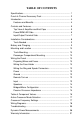
TABLE OF CONTENTS Specifications ................................................................................... 1 Punch 4-Channel Accessory Pack ................................................... 3 Introduction ...................................................................................... 4 Features and Benefits ................................................................. 4 Controls and Features ......................................................................
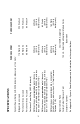
1 35 Watts X 4 Per channel into a 4Ω Load 80 Watts ( @ 12.6 battery volts) RMS continuous power bridged into a 4Ω load from 20 to 20,000 Hz, with less than 0.1% Total Harmonic Distortion (THD) Butterworth 100 Hz - Selectable with optional Module Cards See Appendix A - Dynamic Power Measurements for information on these specifications. 1 Crossover Alignment Factory Default Crossover Point 160 Watts ( @ 13.8 battery volts) 80 Wattls ( @ 13.8 battery volts) 40 Watts ( @ 13.
2 9-5/8" (24.4cm) W 13-5/8" (34.6cm) L 2-5/8" ( 6.6cm) H Input Impedance Equalization AGU ATC Specifications subject to change without notice. 20k ohms Bass: +18dB Maximum at 45Hz Treble: +12dB Maximum at 20kHz 50 Amps 30 Amps Internal analog-computer output protection circuitry limits power in case of overload. Thermal switch shuts down the amplifier in case of overheating.
PUNCH 4-CHANNEL ACCESSORY PACK 12' (366cm) Blue Remote Turn-on Wire 17' (518cm) Red Power Wire 1.
INTRODUCTION This manual provides information on the features, installation, and operation of the Punch 4040 DSM and 4080 DSM Amplifiers. We suggest you save this manual for future reference. We strongly recommend you have your Authorized Rockford Fosgate Dealer install your new Punch 4-channel amplifier. If you do choose to install the amplifier yourself, please be sure to read the entire manual before beginning.
Real Time Power Protection (R.T.P.P.) allows for the greatest power output under all load conditions. When output reaches an unsafe level it will be reduced, unlike current limiting which often causes premature protection or failure to protect at all. To get a better understanding of the Punch let’s take a closer look. CONTROLS AND FEATURES This section describes the various controls and features of the Punch 4040 DSM and 4080 DSM amplifiers.
Mounting Screws Four (4) custom, round, hex screws included in the accessory pack hold the unit in place. These screws are covered when the end caps are installed.
Input/Output Terminal Side Front Treble Front Input Adjustment Gain Control Control Front Input Connectors Front Bass Adjustment Control Front+Rear Summed Pass-Thru Connectors Rear Treble Adjustment Control Rear Input Connectors Rear Input Gain Control 0/180° Rear Phase Selector Switch Rear Bass Adjustment Control Front/Rear Input Switch Front/Rear Input Switch This switch allows you to use the front input to drive both Front and Rear channels.
Input Connectors The amplifier’s signal input, female, RCA jacks should be connected to the source unit’s signal outputs with highquality RCA cables. The connectors have been plated in gold to eliminate the possibility of corrosion that can cause signal deterioration. Front & Rear Summed Pass-Thru Connectors These pass-thru connectors allow you to daisy-chain an additional Punch amplifier without running an additional set of RCA cables from the front of the vehicle to the rear amplifier location.
4. Think before you drill! Be careful not to cut or drill into gas tanks, fuel lines, brake or hydraulic lines, vacuum lines or electrical wiring when working on any vehicle. 5. For safety, disconnect the battery ground cable prior to beginning the installation process. 6. Never run wires underneath the vehicle. The cleanest, safest wiring connections are made by running the wire under the carpet or behind the side panels. Never leave wires exposed. 7. Avoid running wires over or through sharp edges.
MOUNTING AND LOCATION The mounting location and position of the Punch 4Channel will have a great effect on its ability to dissipate the heat generated in normal operation. The Punch 4Channel has a heatsink designed for heat dissipation and internal shutoff circuitry to avoid overheating. It is reasonably tolerant of mounting variations. However, care should be taken to ensure adequate ventilation. Trunk Mounting The temperature inside a trunk can reach as high as 175° F (80° C) during the summer months.
2. For the Punch 4040, place the protective boot onto the wire. Insert the wire into one end of the fuse holder so that the insulation is just inside the crimp area as shown in the diagram. Crimp the wire in place with the notched portion of a crimping tool. Cover the crimped area with the protective boot that is supplied with the fuse holder. { Crimp Here Fuse Holder Protective Boot 3. For the Punch 4080, place the protective boot onto the wire. Slide the wire into the wire sleeve.
Wiring the Ring and Spade Connectors 1. Strip back approximately 3/8" (1cm) of insulation. 3/8" (1cm) 2. Insert the bare wire into the connector and crimp in place as shown in the following diagram: This connector is used for the Red Power wire and Black Ground wire. Crimp Here { Connectors { Wire w/insulation This connector is for the Blue Remote Turn-On wire.
INSULATION STRIP WIRE > < 5/8" > > AMP > Ground The GND terminal grounds the amplifier and is connected to the chassis of the vehicle with 12 gauge, or heavier, stranded wire. When grounding, scrape paint off metal to ensure a good, clean ground connection. To prevent ground loops, we recommend you refrain from extending the ground wire beyond 18" (46cm) in any installation. Remote Turn-on The Punch 4-Channel amplifiers are turned on by supplying positive (+) 12 volts to the REM terminal.
Speakers Punch 4-Channel amplifiers are rated for safe operation into loads of 2Ω, or greater in stereo mode or 4Ω in bridged/mono configurations. The primary loads on any amplifier come from directly connected speakers without using capacitors. The measured resistance for each side should not be less than 2Ω stereo or 4Ω bridged/mono. Bridged/Mono Configuration The Punch 4-Channel amplifiers are capable of bridged/ mono configurations.
The most commonly used filter networks are 6 dB per octave systems. These are easy to construct and require a minimum number of parts. A filter network can perform one of three functions. These are highpass (capacitors), lowpass (inductors, chokes or coils) and bandpass (combination of a capacitor and a coil). The result, limiting the types of frequency to the speaker, is directly dependent upon the speaker’s impedance and component values.
Table of Component Values C L 6 dB/Octave Low Pass Freq. Hertz 6 dB/Octave High Pass Speaker Impedance 2 OHMS 8 OHMS 4 OHMS L C L 80 100 130 4.1mH 3.1mH 2.4mH 1000µF 800µF 600µF 8.2mH 6.2mH 4.7mH 200 260 400 1.6mH 1.2mH .8mH 400µF 300µF 200µF 600 800 1000 .5mH .41mH .31mH 1200 1800 4000 6000 9000 12000 C L C 500µF 400µF 300µF 16mH 12mH 10mH 250µF 200µF 150µF 3.3mH 2.4mH 1.6mH 200µF 150µF 100µF 6.8mH 4.7mH 3.3mH 100µF 75µF 50µF 136µF 100µF 78µF 1.0mH .82mH .
The Punch 4-Channel amplifiers feature selectable electronic crossovers. Selection is made by positioning of a removable module card. These modules control the output channels and can be configured in a High Pass, Low Pass or Full Range (factory default) position. The 4Channel amplifiers are shipped with 100Hz 12dB per octave Butterworth aligned crossover modules. Additional crossover frequency modules are available from your Authorized Rockford Fosgate Dealer.
SAMPLE WIRING DIAGRAMS SOURCE UNIT IN OUT IN R R L L 0 TREBLE GAIN BASS TREBLE GAIN FRONT FRONT FRNT+REAR BASS 180 R F PHASE INPUT REAR REAR Input switch set to F Front crossover set to 100 Hz High Pass Rear crossover set to 100 Hz Low Pass Front+Rear summed output not used Phase switch set to 0° * REM REAR (bridge) + LEFT– B+ GND FRONT (bridge) +RIGHT– + + LEFT– +RIGHT– – 4Ω Woofer – + – + 4 Ohm (2Ω min.) 4 Ohm (2Ω min.
SOURCE UNIT Left Right IN OUT IN R R L L 0 TREBLE GAIN BASS TREBLE GAIN FRONT FRONT FRNT+REAR BASS 180 R F PHASE INPUT REAR REAR Input switch set to R Set Front & Rear crossover to the same point Front+Rear summed output not used Phase switch set to 0° * REM REAR (bridge) + LEFT– +RIGHT– + – 4Ω Right B+ GND FRONT (bridge) + LEFT– +RIGHT– + – 4Ω Left 2-CHANNEL BRIDGED STEREO * In this mode the phase switch should always be at 0°.
SOURCE UNIT IN OUT R IN R 0 TREBLE GAIN BASS TREBLE GAIN FRONT L FRONT L FRNT+REAR BASS 180 R F PHASE INPUT REAR REAR Input switch set to F Set Front & Rear crossover to the same point Front+Rear summed output not used Phase switch set to 180° * REM REAR (bridge) + LEFT– B+ GND FRONT (bridge) +RIGHT– + LEFT– Left – Right + 4Ω Subwoofer +RIGHT– + – 4Ω Subwoofer 2-CHANNEL BRIDGED STEREO * In this mode the phase switch should always be at 180°.
SOURCE UNIT IN OUT IN R R L L 0 TREBLE GAIN BASS TREBLE GAIN FRONT FRONT FRNT+REAR BASS 180 R F PHASE INPUT REAR REAR Input switch set to F Front crossover set to 100 Hz High Pass Rear crossover set to 100 Hz Low Pass Front+Rear summed output not used Phase switch set to 0° * REM + LEFT– – +RIGHT– GND +RIGHT– + + LEFT– B+ FRONT (bridge) – REAR (bridge) + 4 Ohm (2Ω min.) 4 Ohm (2Ω min.
SOURCE UNIT IN OUT R IN R 0 TREBLE GAIN BASS TREBLE GAIN FRONT L FRONT L FRNT+REAR BASS 180 R F PHASE INPUT REAR REAR Input switch set to Rear Front crossover set to Full Range Rear crossover set to Full Range Front+Rear summed output not used Phase switch set to 0° REM + LEFT– GND +RIGHT– – + Full Range – + – + Full Range +RIGHT– + + LEFT– B+ FRONT (bridge) 4Ω (2Ω min.) Mid Range/ Tweeter 4Ω (2Ω min.
SOURCE UNIT IN OUT R IN R 0 TREBLE GAIN BASS TREBLE GAIN FRONT L FRONT L FRNT+REAR BASS 180 R F PHASE INPUT REAR REAR Input switch set to Rear Front crossover set to Full Range Rear crossover set to Full Range Front+Rear crossover set to 100Hz Low Pass Phase switch set to 0° REM + LEFT– GND +RIGHT– – + – + – Full Range + Full Range Full Range Full Range LR +RIGHT– + + LEFT– B+ FRONT (bridge) – REAR (bridge) RL L + BIAMPLIFIED 4-CHANNEL with SUBWOOFER AMP R – Subw
SOURCE UNIT IN OUT IN R R L L 0 TREBLE GAIN BASS TREBLE GAIN FRONT FRONT FRNT+REAR BASS 180 R F PHASE INPUT REAR REAR Input switch set to F Set Front & Rear crossovers to the same point Front+Rear summed output not used Phase switch set to 0° * REM REAR (bridge) + LEFT– FRONT (bridge) +RIGHT– + – 4Ω Woofer + LEFT– +RIGHT– + – 4Ω Woofer BRIDGED MONO 24 B+ GND
TROUBLESHOOTING Problem Amplifier will not play – Remote turn-on light is off. Solution 1. Check the DC voltage at the amplifier's B+ terminal with a voltmeter. The voltage should measure between 11.5V - 15.5V. If voltage is not found, check the battery, fuse, fuse housing and wire connections. Fix, repair, or replace accordingly. 2. If the amplifier still does not play, check the voltage at the amplifier's remote turn-on lead. The voltage should measure between 11V - 15V. a.
Problem Amplifier gets too hot. Solution 1. Be sure the amplifier is properly mounted. You should be able to place your hand a few inches above the amplifier housing and feel the heat rising when the unit is on. Hot air rises, consequently, mount the amplifier with the heatsink fins aligned vertically. This allows the air to flow freely, carrying away the heat. Check to see that the heatsink fins are free of any obstruction (i.e., carpet, seats, etc.). 2.
Problem Engine Noise (Whine) Solution 1. Disconnect the speakers from the amplifier. Connect a test speaker to the amplifier output terminals. If the noise goes away, check your speaker leads, speakers and crossovers. 2. If the noise persists, use a "shorting plug" to mute the input signal at the amplifier. If the noise goes away: a. Bypass all of the other equipment (i.e., crossovers and equalizers) and connect the head unit directly to the amp.
DYNAMIC POWER MEASUREMENTS About the Dynamic Power Measurements The Audio Graph PowerCube is a test instrument used to measure the output of an amplifier in accordance with IHF-202 industry standards. The IHF-202 standard is a Dynamic power measurement and was developed as a means of measuring power in a manner that best represents the Real World operation of an amplifier. Many manufacturers, including Rockford Fosgate, at times will measure amplifier power into a fixed resistor (4 ohm, 2 ohm).
A 4 ohm speaker may experience a drop in impedance 46 times lower than its nominal (printed) impedance. A speaker will also create phase shifts in the signal that is passed through it. These phase shifts happen because a speaker is an inductor (voice coil) and a capacitor (compliance of the surround/spider), as well as a resistor (voice coil wire). To simulate a speaker the Audio Graph PowerCube measures output power into 20 different loads. It tests at 8 ohms, 4 ohms, 2 ohms and 1 ohm.
What is an Amplifier? An amplifier by definition is a voltage generating device, recreating the signal which is input to in an identical but amplified form. It will be connected to a reactive load (the speaker). The impedance of this load and phase of the signal passing through the load will vary, dependent upon the frequency and amplitude of the input signal (music).
WARRANTY INFORMATION Rockford Fosgate warrants all electronics to the original consumer/purchaser to be free from defects in materials or workmanship for a period of three (3) years. We will cover parts and labor provided the product was purchased from an Authorized Rockford Fosgate Dealer. This warranty does not apply to any product on which the seals and/or serial number have been broken, removed, tampered with, defaced or altered in any manner.
Rockford Fosgate A Division of Rockford Corporation 546 South Rockford Drive Tempe, Arizona 85281 U.S.A. In U.S.A., (602) 967-3565 In Canada, call Korbon (416) 567-1929 In Europe, Fax (49) 4207-801250 REV.