® ® ® ® ® 2-CHANNEL AMPLIFIERS OPERATION & INSTALLATION ® ®
Dear Customer, Congratulations on your purchase of the world's finest brand of car audio amplifiers. At Rockford Fosgate we are fanatics about musical reproduction at its best, and we are pleased you chose our product. Through years of engineering expertise, hand craftsmanship and critical testing procedures, we have created a wide range of products that reproduce music with all the clarity and richness you deserve.
TABLE OF CONTENTS Introduction ............................................................................................. 1 Punch Amplifier Accessory Pack .............................................................. 1 Technical Design Features ....................................................................... 2 Design Features ........................................................................................ 5 Installation Considerations ...................................................
INTRODUCTION Rockford engineers designed the Punch 40x2, 60x2, 100x2 and 200x2 amplifiers to withstand the rugged automotive environment while delivering superior sound quality in a flexible, reliable, and efficient package. TRANS•ANA is a low voltage circuit in the preamp stage of all Punch x2 amplifiers that lets the music sound crystal clear and very real, even when played at high volume levels.
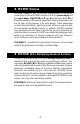
T ECHNICAL D ESIGN F EATURES ◆ TRANS•ANA (TRANSconductance Active Nodal Amplifier) The TRANS•ANA (TRANSconductance Active Nodal Amplifier) is a circuit that allows the audio signal to pass through the amplifier at low voltage. The signal is directly level-shifted to the fixed high voltage rails via a pair of driver transistors. Signal linearity is assured by an active node formed by the drive transistors at ultrasonic frequencies.
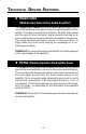
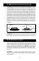
◆ DSM (Discrete Surface Mount) Technology The DSM (Discrete Surface Mount) manufacturing process combines the advantages of both discrete components and integrated circuitry. Rockford Fosgate is the only American amplifier manufacturer to have invested millions into this process. DSM components differ from conventional discrete components in different ways. They are more compact, more rugged, and they efficiently dissipate generated heat.
◆ MOSFET Devices Rockford Fosgate is one of the few manufacturers in the sound community to utilize MOSFET devices in both the power supply and the output stages. MOSFET (Metal Oxide Semiconductor Field Effect Transistor) devices offer several important inherent advantages over the 30 year old technology of bi-polar design. These advantages include: thermal stability, switching speed, ultra low output impedance and wider bandwidth linearity.
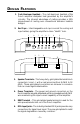
D ESIGN F EATURES 1. Cast Aluminum Heatsink – The cast aluminum heatsink of the Punch amplifier dissipates heat generated by the amplifier's circuitry. The inherent advantage of casting provides a 30% improvement of cooling over conventional extrusion heatsink designs. 2. End Caps – Interchangeable end caps conceal the wiring and input cables, giving the amplifier a clean “stealth” look.
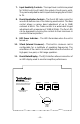
7. Input Sensitivity Controls – The input level controls are preset for 500mV which will match the output of most source units. They can be adjusted to match input levels ranging from 150mV to 3V. 8. Punch Equalization Controls – The Punch EQ helps correct for acoustical deficiencies of the listening environment. The Bass control allows a narrow band adjustment of up to 18dB centered at 45Hz. The Treble control is a wide band hinged adjustment with a maximum of 12dB at 20kHz.
I N S TA L L AT I O N C O N S I D E R AT I O N S The following is a list of tools you will need for installing the Punch amplifier: Allen wrenches 7/64" & 3/32" (included) Voltmeter Wire strippers Battery post wrench Electric hand drill w/assorted bits Wire cutters 17' (518.16cm) Red Power Wire Assorted connectors 12' (365.76cm) Remote Turn-On Wire Wire crimpers 1.5' (45.72cm) Black Grounding Wire This section focuses on some of the vehicle considerations for installing your new Punch amplifier.
M OUNTING L OCATION The mounting location and position of your amplifier will have a great effect on its ability to dissipate the heat generated during normal operation. The design of our cast aluminum heatsink serves to easily dissipate the heat generated over a wide range of operating conditions. However, to maximize the performance of your amplifier, care should be taken to ensure adequate ventilation.
B ATTERY AND C HARGING Amplifiers will put an increased load on the vehicle's battery and charging system. We recommend checking your alternator and battery condition to ensure that the electrical system has enough capacity to handle the increased load of your stereo system. Stock electrical systems which are in good condition should be able to handle the extra load of any Rockford amplifier without problems, although battery and alternator life can be reduced slightly.
Punch 40x2, 60x2, 100x2 Trim the power cable to within 18" of the battery and install the protective rubber boot, which is packed with the fuseholder, over the end of the wire. Strip 3/8" of insulation from the wire and insert into the end of the fuseholder, then crimp it in place. Slide the rubber boot into place to cover the connection. Use the section of cable that was trimmed earlier and connect it to the other end of the fuseholder.
6. Prepare the REM turn-on wire for connection to the amplifier by stripping 5/8" of insulation from the wire end and crimping an insulated spade connector in place. Slide the connector over the REM terminal on the amplifier. Connect the other end of the REM wire to a switched 12 volt positive source. The switched signal is usually taken from the source unit's auto antenna or the accessory lead.
USING THE XCARD The crossover functions are controlled through the use of an XCard and can be set for high-pass, low-pass or full range operation. The 100Hz XCard shipped with your amplifier is set for Full Range. Each crossover card has two faces: one face operates Full Range, the other has arrows to indicate the edge for selecting HP (high-pass) or LP (lowpass) operation. Orient the card with the desired operating edge, indicated by the arrow, toward the socket terminals inside the amplifier.
R ESISTOR C HART ▲ Use the resistor charts below to modify the factory shipped 100Hz XCard. Butterworth Alignment Q = .707 µF caps 1% resistors used with 0.047µ Frequency R1 R2 20Hz 25Hz 169kΩ 133kΩ 169kΩ 133kΩ 30Hz 35Hz 110kΩ 95.3kΩ 40Hz 45Hz Butterworth Alignment Q = .707 µF caps 5% resistors used with 0.047µ Frequency R1 R2 21Hz 26Hz 160kΩ 130kΩ 160kΩ 130kΩ 110kΩ 95.3Ω 30.8Hz 37Hz 110kΩ 91kΩ 110kΩ 91Ω 84.5kΩ 75kΩ 84.5kΩ 75kΩ 41Hz 45Hz 82kΩ 75kΩ 82kΩ 75kΩ 50Hz 55Hz 68.1kΩ 61.
I NSTALLATION ® Power Connections LED REM Connect to remote turn-on lead of source unit B+ GND Punch Status Display Connect to chassis ground of vehicle* Less than 18" P40x 2 P60x 2 P100x 2 P200x Connect to B+ of battery with appropriate fuse value *Keep grounds as short as possible – 14 – 2 - 20A - 30A - 40A - 50A ® I N S T A L L A T I O N
® Stereo Operation RCA Input Speaker + L – Treble Left Gain Left Input Right Input Right Gain – Speaker + R – + 2Ω min. 2Ω min.
® Mono Operation RCA Input Speaker + L – Treble Left Gain Left Input Right Input + Right Gain Bass Speaker + R – – 4Ω min.
® Stereo/Mono Operation RCA Input Speaker + L – Treble Left Gain Left Input Right Input Right Gain Bass Speaker + R – + – 2Ω min. 2Ω min. – + + – 4Ω min.
SYSTEM DIAGRAMS 2-Way System R AUD VOL PWR DISC AMFM ® ST Ch LD RDM RPT CLOCK AUTO DSPL P.SCN SEL ILLUM LOUD D.
3-Way System R AUD VOL PWR CLOCK DISC AMFM ® ST Ch LD RDM RPT AUTO DSPL SEL ILLUM P.SCN LOUD D.
4-Way System R AUD VOL DISC AMFM PWR ST ® Ch LD RDM RPT CLOCK AUTO DSPL P.SCN SEL ILLUM LOUD D.
4-Way System w/Fadable Rear Stage R AUD VOL DISC AMFM PWR Ch LD RDM RPT ST ® CLOCK AUTO DSPL P.SCN SEL ILLUM LOUD D.
R OCK F OR D F OS G ATE A CCE SSORIES ® Punch Status Display (FG-PSD) The Punch Status Display is an LED array which monitors amplifier performance. The PSD is a 2-channel monitor which has an indicator for Power, three indicators for Signal Level (signal-max-clip), and an indicator for Thermal condition. The display is designed to be stackable for multiple amplifier monitoring.
Energy Storage Capacitors The Punch capacitors are used to provide extra current needed by amplifiers to reproduce musical transients. The Punch Caps also have the natural ability to filter AC ripple caused by the alternator, reducing the chance of noise in the system. The Punch Caps are available in a variety of values and will maximize both the sound quality and performance that Rockford Fosgate amplifiers can deliver.
® Punch Link (FG-LINK) The Punch Link is a specially cast heatsink interconnect which allows you to join any of our current Punch or Punch Power amplifiers together. While providing additional cooling through the coupling process, the Punch Link adds the finishing touch by giving you the look of one awesome amplifier.
XCard Crossovers Additional crossover card frequencies are available for specialized requirements. You can get the following XCards from your Authorized Rockford Fosgate Dealer. XM50 XM70 XM100 XM150 XM200 = 50Hz = 70Hz = 100Hz = 150Hz = 200Hz XM275 XM400 XM4.5k XM6.5k XM00 = = = = = 275Hz 400Hz 4,500Hz 6,500Hz Blank card for custom crossover FULL R2 High Pass Low Pass Full Range R1 R2 Crossover Card R1 ® ATTENTION: We recommend your Authorized Rockford Fosgate Dealer install your new accessory.
TROUBLESHOOTING Symptom Amplifier does not turn on (Power LED is off) Amplifier has no sound (Power LED is on) Diagnosis TROUBLE-S H O O T I N G Remedy Voltage applied to the REM terminal of the amplifier is not between 10.5 and 15.5 volts or there is no voltage present. Check the alternator, battery, fuse, and wiring and repair as necessary. If the voltage is above 15.5 volts, have the electrical system inspected by an authorized car service center.
TROUBLE-S H O O T I N G Symptom Speaker Output Low or Distorted Amplifier Noise (Turn-on Pop) Diagnosis Remedy Input gain signal for amplifier is incorrectly set. Readjust input gains of amplifier. Source unit output too low or source unit has no output. Check system with known working source and repair or replace original source as needed. XCard is missing or not placed properly in crossover slots. Check XCard position and repair or replace as necessary.
TROUBLE-S H O O T I N G Symptom Engine Noise Diagnosis Remedy Noise is radiating into RCA signal cable. Check connections, run the RCA cables on a different route away from sources of high current. Bad component in the signal chain. Check connections, bypass additional components (crossovers and equalizers) between the source unit and the amplifier. Connect one component at a time to determine the culprit. Repair or replace components as necessary. Noise is radiating into speaker cables.
DYNAMIC POWER MEASUREMENTS About the Dynamic Power Measurements The Audio Graph PowerCube is a test instrument used to measure the output of an amplifier in accordance with IHF-202 industry standards. The IHF-202 standard is a dynamic power measurement and was developed as a means of measuring power in a manner that best represents the Real World operation of an amplifier. Many manufacturers, including Rockford Fosgate, at times will measure amplifier power into a fixed resistor (4 ohm, 2 ohm).
Information Cubed The data acquired in the testing procedure is then graphed in the form of a 3-dimensional cube, hence the name PowerCube. The Phase Angle is expressed on the horizontal axis, the Output Voltage is presented on the vertical axis and the Impedance is displayed on the Z axis. Output Power, in watts, is listed on the left hand side for each impedance at each phase angle. Audio Graph – The PowerCube™ x2 = STEREO MONO = BRIDGED MONO I M P E D A N C E Amplifier: PUNCH 200x2 14.
– 31 – PUNCH 40x2 60 Watts Per channel into a 4Ω Load 80 Watts 135 Watts 270 Watts PUNCH 60x2 Signal-to-Noise Ratio RMS continuous power mono into a 4Ω load from 20 to 20,000 Hz, with less than 0.1% Total Harmonic Distortion (THD) RMS continuous power per channel, both channels driven into a 2Ω load from 20 to 20,000 Hz, with less than 0.1% Total Harmonic Distortion (THD) RMS continuous power per channel, both channels driven into a 4Ω load from 20 to 20,000 Hz with less than 0.
– 32 – Input Impedance Equalization Battery Fusing Rates (External to Amplifier) Fuse Type Protection Input Sensitivity IM Distortion (IHF) Slew Rate Frequency Response PUNCH 100x2 PUNCH 200x2 Variable from 150mV to 3V Preset at the factory for 500mV <0.05% 50 Volts µs 20Hz to 20kHz ±.05dB / 10Hz to 100kHz ±1.0dB >200 10Hz to 200kHz ±3dB 9-5/8" (24.4cm) W 9-5/8" (24.4cm) W 9-5/8" (24.4cm) W 9-5/8" (24.4cm) W 9-5/8" (24.4cm) L 10-5/8" (27.0cm) L 11-5/8" (29.5cm) L 12-5/8" (32.
W A R R A N T Y I N F O R M AT I O N Rockford Fosgate warrants all electronics to the original consumer/purchaser to be free from defects in materials or workmanship for a period of three (3) years. We will cover parts and labor provided the product was purchased from an Authorized Rockford Fosgate Dealer. This warranty does not apply to any product on which the seals and/ or serial number have been broken, removed, tampered with, defaced or altered in any manner.
A T N A TI M IO R R TE O N FO N IN A L IN – 34 –
LEA DETENIDAMENTE LAS SIGUIENTES INSTRUCCIONES DE INSTALACION DEL PRODUCTO. EVITARA POSIBLES DAÑOS A VD., AL VEHICULO O AL PRODUCTO. INTRODUCCION Los ingenieros de Rockford han diseñado los amplificadores Punch x2 para ofrecer en el dificil entorno de un automóvil una calidad de sonido superior en un producto flexible, fiable y eficiente.
Terminal REM Conecte el cable REM a un punto de +12V con mutable. La señal se suele coger de la salida auto antena del radio cassette si este no tiene salida remote. Funcionamiento Estereo/Mono RCA Input Speaker + L – Treble Left Gain Left Input Right Input Right Gain Bass Speaker + R – + – 2Ω min. 2Ω min. – + + – 4Ω min. • Las entradas RCA se conectan a ambos canales izquierdo y derecho. • Las ganancias izquierda y derecha han de ajustarse igual para ambos canales.
ATTENTION: Veuillez lire les instructions suivantes pour l'installation de cet amplifcateur. Ne pas les suivre pourrait causer des blessures ou endommager le véhicule. INTRODUCTION Les ingénieurs de Rockford Fosgate ont conçu l'amplificateur Punch x2 pour supporter l'environnement rude de l'automobile en délivrant une qualité de son supérieure dans un ensemble efficace, fiable et flexible.
Terminal GND Préparez une longueur de câble pour la connexion à la masse. Préparez le châssis en grattant la peinture de la surface métallique et nettoyez la saleté et l'huile. Attachez le câble au châssis avec une vis. Terminal REM Connectez le fil REM à une commande 12 volts positive de la source. La commande 12 volts est habituellement prise sur la sortie antenne électrique de la source ou la commande accessoire.
BITTE LESEN SIE DIESE GEBRAUCHSANLEITUNG ZUERST SORGFÄLTIG DURCH. DAS KANN SIE VOR DEM FALSCHEN EINSATZ, AUSFALLEN ODER SOGAR BESCHÄDIGUNG DES PRODUKTES ODER IHRES FAHRZEUGES SCHÜTZEN. EINLEITUNG Rockford Ingenieure haben die Punch x2 Verstärker entwickelt.
GND Anschluss Preparieren Sie Ihr Kabel für die Negativ Leitung (Erdung). Preparieren Sie die Anschluβstelle des Erdungskabels, indem Sie das Metall gründlich reinigen und vom Lack befreien. Befestigen Sie nun die Erdung an dieser Stelle mit einer Schraube. REM Anschluss Verbinden Sie das Ein-und Ausschaltungskontroll-Kabel mit Ihrem Radio (12 Volt positiv). Normalerweise verwenden Sie hierfür die Ant.-Remote Ihres Radios oder ein eigens dafür vorgesehenes Kabel (Amp-Remote).
ATTENZIONE: SI PREGA DI LEGGERE LE SEGUENTI ISTRUZIONI PER L'INSTALLAZIONE DI QUESTO PRODOTTO. IL NON SEGUIRLE POTREBBE RISULTARE SERIAMENTE DANNOSO PER LA PERSONA O PER IL VEICOLO. INTRODUZIONE Gli ingenieri Rockford hanno progettato la serie di amplificatori Punch x2 per resistere all'ostico ambiente automobilistico mentre suonano con una musicalitá superiore, offrendo un insieme versatile, affidabile ed efficiente.
Terminale GND (cavo negativo) Decidere la lunghezza del cavo e terminarlo. Preparare la massa grattando la vernice dal telaio dell'auto ed eliminando tracce di olio o sporco. Fissare il cavo di massa al telaio con una vite. Terminale REM (Consenso di accensione) Collegare il cavo REM ad un positivo presente solo ad autoradio accesa (normalmente il cavo pilota dell'antenna elettrica o il cavo accessori dell'autoradio).
NOTES
NOTES
MADE IN THE USA This product is designed, developed and assembled in the USA by a dedicated group of American workers. The majority of the components used in the construction of this product are produced by American companies. However, due to the global nature of their manufacturing facilities and the loudspeaker parts industry in general, some parts may be manufactured in other countries. Rockford Fosgate Rockford Corporation 546 South Rockford Drive Tempe, Arizona 85281 U.S.A. In U.S.A.