® ® car audio for fanatics 390 Watt Amplifier 5-channel w/crossovers Installation and Operation
Dear Customer, Congratulations on your purchase of the world's finest brand of car audio amplifiers. At Rockford Fosgate we are fanatics about musical reproduction at its best, and we are pleased you chose our product. Through years of engineering expertise, hand craftsmanship and critical testing procedures, we have created a wide range of products that reproduce music with all the clarity and richness you deserve.
TABLE OF CONTENTS Introduction ............................................................................................. 1 Accessory Pack ........................................................................................ 1 Technical Design Features ....................................................................... 1 5.3x Design Features ................................................................................ 5 Installation Considerations ............................................
INTRODUCTION The RF 5.3x is a 5-channel amplifier with four stereo channels and a single bridged/mono channel for accommodating “single amplifier” system designs at a competitive price. Since this manual provides information on the features, installation and operation of the Rockford Fosgate 5.3x amplifier, we suggest you save it for future reference. We strongly recommend you have your Authorized Rockford Fosgate Dealer install your new Rockford Fosgate amplifier.
◆ TOPAZ (Tracking Operation Pre-Amplifier Zone) The TOPAZ (Tracking Operation Pre-Amplifier Zone) circuitry solves ground loop noise problems common to automotive amplifier design. This innovative new development allows vastly improved isolation of the input signal grounds from the power supply ground of the amplifier. This is accomplished by allowing the source unit to control the potential “environment” of the entire input structure or “zone” of the amplifier.
◆ DSM (Discrete Surface Mount) Technology The DSM (Discrete Surface Mount) manufacturing process combines the advantages of both discrete components and integrated circuitry. Rockford Fosgate is the only American amplifier manufacturer to have invested millions into this process. DSM components differ from conventional discrete components in different ways. They are more compact, more rugged, and they efficiently dissipate generated heat.
◆ High Level Inputs The high level inputs on the Rockford Fosgate amplifiers convert the speaker line outputs (high level) to preamp line inputs (low level). This allows amplifier compatibility with a variety of source units as well as the ability to integrate into factory systems without the need for external adapters. THE RESULT: Allows compatibility with factory and aftermarket source units. ◆ XCard Crossover The 5.3x amplifiers utilize internal active crossovers.
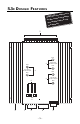
5.3X D E S I G N F E AT U R E S nt to djustme ge C y dama trols ma n o c s void the Bia nd will plifier a m a r u o y .
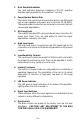
1. Dual Extruded Heatsinks The dual extruded aluminum heatsinks of this RF amplifier dissipate heat generated by the amplifier's circuitry. 2. Power/Speaker Barrier Strip The barrier strip uses screw terminals that will accept #10 spade lugs or bare speaker and power wire sizes from 10-18 AWG. These gold-plated connectors are immune to corrosion that will cause signal degradation. 3. RCA Input Jacks The industry standard RCA jack provides an easy connection for signal level input.
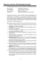
I N S TA L L AT I O N C O N S I D E R AT I O N S The following is a list of tools you will need for installing the amplifier: Wire Cutters Wire Strippers Wire Crimpers Voltmeter #2 Phillips Screwdriver Assorted wire connectors Battery Post Wrench Electric Hand Drill with assorted bits This section focuses on some of the vehicle considerations for installing your new amplifier.
M OUNTING L OCATION The mounting location and position of your amplifier will have a great effect on its ability to dissipate the heat generated during normal operation. The design of our aluminum heatsink serves to easily dissipate the heat generated over a wide range of operating conditions. However, to maximize the performance of your amplifier, care should be taken to ensure adequate ventilation.
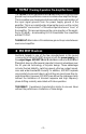
B ATTERY AND C HARGING Amplifiers will put an increased load on the vehicle's battery and charging system. We recommend checking your alternator and battery condition to ensure that the electrical system has enough capacity to handle the increased load of your stereo system. Stock electrical systems which are in good condition should be able to handle the extra load of any Rockford amplifier without problems, although battery and alternator life can be reduced slightly.
Trim the power cable within 18" of the battery and strip 1/2" of insulation from the end of the wire. Cut the wire loop that is attached to the fuseholder in half and splice the fuse into the power line using appropriate inline connectors. Use the section of cable that was trimmed earlier and connect it to the other end of the fuseholder. X Cut here 4. Strip 1/2" from the battery end of the power cable and crimp a large ring terminal to the cable.
USING PASSIVE CROSSOVERS A passive crossover is a circuit that uses capacitors and/or coils and is placed on speaker leads between the amplifier and speaker. The crossover delegates a specific range of frequencies to the speaker for optimum driver performance. A crossover network can perform one of three functions: High-Pass (capacitors), Low-Pass (inductors or coils) and Bandpass (combination of capacitor and coil). The most commonly used passive crossover networks are 6dB/octave systems.
TABLE OF CROSSOVER COMPONENT VALUES C L 6 dB/Octave Low-Pass 6 dB/Octave High-Pass Speaker Impedance Freq. Hertz 2 OHMS 8 OHMS 4 OHMS L C L 80 100 130 4.1mH 3.1mH 2.4mH 1000µF 800µF 600µF 8.2mH 6.2mH 4.7mH 200 260 400 1.6mH 1.2mH .8mH 400µF 300µF 200µF 600 800 1000 .5mH .41mH .31mH 1200 1800 4000 6000 9000 12000 C L C 500µF 400µF 300µF 16mH 12mH 10mH 250µF 200µF 150µF 3.3mH 2.4mH 1.6mH 200µF 150µF 100µF 6.8mH 4.7mH 3.3mH 100µF 75µF 50µF 136µF 100µF 78µF 1.0mH .82mH .
USING THE XC ARD The crossover functions are controlled through the use of an XCard and can be set for high-pass, low-pass or full range operation. Each crossover card has two faces: one face operates Full Range, the other has arrows to indicate the edge for selecting HP (high-pass) or LP (lowpass) operation. Orient the card with the desired operating edge, indicated by the arrow, toward the socket terminals inside the amplifier. Firmly, but carefully, plug the card into the socket.
a d v a n c e d R ESISTOR C HART O p e r a t i o n Our tests have shown that using 0.047µf capacitors for frequencies below 100Hz, and 0.022µf capacitors for frequencies above 100Hz, result in more linear crossover control. Refer to the Specifications page to determine the capacitor value of each supplied XCard. Butterworth Alignment Q = .707 Butterworth Alignment Q = .707 1% resistors used with 0.047µF caps 1% resistors used with 0.
XC ARD A CCESS The internal XCard crossover(s) are accessible by removing the top cover from the amplifier. The XCard should be inserted with the filter side (HP, LP or FULL RANGE) facing the metal contacts inside the socket.
USING THE SIGNAL SWITCHING NETWORK The Signal Switching Network allows the RCA input signals to be distributed to the outputs in many different configurations. The orientation of both switches configure the distribution pattern . The switches can be oriented in the following configurations.
Configuration #4 (Mono Sub Input) SUB XCard Front inputs => Front & Rear outputs Subwoofer (L Mono) input => Subwoofer outputs FRONT XCard REAR XCard Configuration #5 SUB XCard FRONT XCard Front inputs => Front & Rear outputs Subwoofer inputs => Subwoofer outputs REAR XCard Configuration #6 SUB XCard FRONT XCard Front inputs => Front, Rear & Subwoofer outputs REAR XCard – 17 –
Configuration #1 Front inputs => Front outputs Rear inputs => Rear outputs Subwoofer (L Mono) inputs => Subwoofer outputs SUB XCard FRONT XCard REAR XCard LED LF LR L-Subwoofer RF RR R-Subwoofer A A +LF– +RF– GND +LR– +RR– High Level Inputs Front Gain Rear Gain Sub Gain B B (L Mono) C 390 Watts Total Power ® ® LF+ LF- A RF- RF+ A LR+ LR- B RR- RR+ B – 18 – B+ REM GND SUB + SUB – C
Configuration #2 Front inputs => Front outputs Rear inputs => Rear outputs Subwoofer inputs => Subwoofer outputs SUB XCard FRONT XCard REAR XCard LED LF LR L-Subwoofer RF RR R-Subwoofer A A B B +LF– +RF– GND +LR– +RR– High Level Inputs Front Gain Rear Gain Sub Gain C C 390 Watts Total Power ® ® LF+ LF- A RF- RF+ A LR+ LR- B RR- RR+ B – 19 – B+ REM GND SUB + SUB – C
Configuration #3 Front inputs => Front outputs Rear inputs => Rear outputs Front & Rear inputs summed => Subwoofer outputs Factory Default Setting SUB XCard FRONT XCard REAR XCard LED LF LR L-Subwoofer RF RR R-Subwoofer A A B B +LF– +RF– GND +LR– +RR– High Level Inputs Front Gain Rear Gain Sub Gain 390 Watts Total Power ® ® LF+ LF- A RF+ RF- A LR+ LR- B RR- RR+ B – 20 – B+ REM GND SUB + SUB – A&B
Configuration #4 (Mono Sub Input) Front inputs => Front & Rear outputs Subwoofer (L Mono) inputs => Subwoofer outputs SUB XCard FRONT XCard REAR XCard LED LF LR L-Subwoofer RF RR R-Subwoofer +LF– +RF– GND +LR– +RR– High Level Inputs Front Gain Rear Gain Sub Gain A A (L Mono) C 390 Watts Total Power ® ® LF+ LF- A RF- RF+ A LR+ LR- A RR- RR+ A – 21 – B+ REM GND SUB + SUB – C
Configuration #5 Front inputs => Front & Rear outputs Subwoofer inputs => Subwoofer outputs SUB XCard FRONT XCard REAR XCard LED LF LR L-Subwoofer RF RR R-Subwoofer A A +LF– +RF– GND +LR– +RR– High Level Inputs Front Gain Rear Gain Sub Gain C C 390 Watts Total Power ® ® LF+ LF- A RF- RF+ A LR+ LR- A RR- RR+ A – 22 – B+ REM GND SUB + SUB – C
Configuration #6 Front inputs => Front, Rear & Subwoofer outputs SUB XCard FRONT XCard REAR XCard LED LF LR L-Subwoofer RF RR R-Subwoofer +LF– +RF– GND +LR– +RR– High Level Inputs Front Gain Rear Gain Sub Gain A A 390 Watts Total Power ® ® LF+ LF- A RF- RF+ A LR+ LR- A RR- RR+ A – 23 – B+ REM GND SUB + SUB – A
5.3X INSTALLATION ® High Level Input – “Single Ended” Type This configuration is used for source units that have “Single Ended” speaker outputs. Only the “+” output is “hot,” whereas the “–” or “common” are common grounded. To verify your source unit has these outputs, connect an ohm meter across the “–” output and radio chassis for a reading of 0Ω. R AUD VOL DISC AMFM PWR ST ® Ch LD RDM RPT LF LR L-Subwoofer RR R-Subwoofer P.
® High Level Input – “B.T.L.” Type This configuration is used for source units that have “B.T.L.” speaker outputs (Bridged Transformer Less not Bacon Tomato & Lettuce). Both “+” and “–” outputs are considered “hot” or “floating.” Factory Radio + – R– R+ Front LF LR L-Subwoofer RF RR R-Subwoofer +LF– Rear L+ L– R+ R– L– L+ LED ^ v 100.
® Power Connections 390 Watts Total Power ® SUB + ® LF+ LF- RF- RF+ LR+ LR- RR- RR+ B+ Connect to remote turn-on lead of source unit REM GND SUB – Connect to chassis ground of vehicle Less than 18" Connect to B+ of battery with 30A fuse 3-Channel Operation 390 Watts Total Power ® SUB + ® LF+ LF- RF+ RF- – + 4Ω Min. LEFT LR+ LR- RR- RR+ + – 4Ω Min. RIGHT B+ REM GND – + 4Ω Min.
® 3-Channel Mono Operation 390 Watts Total Power ® SUB + ® LF+ LF- RF- RF+ LR- – + LR+ RR- B+ REM + – 4Ω Min. RR+ GND SUB – – + 4Ω Min. 4Ω Min.
SYSTEM DIAGRAMS 230 Watt System (rated @ 4 ohms) Step #1 Upgrade the factory system with an RF5.3x amplifier and mono subwoofer. LP HP Subwoofer XCard ^ v 100.
230 Watt System (rated @ 4 ohms) Step #2 Further upgrade the factory system by replacing the front factory speakers and adding “rear fill” speakers. LP HP Subwoofer XCard ^ v 100.
350 Watt System (rated @ 4 ohms) Step #3 Replace the factory source unit with an RFX-8030, adding a 4.6x amplifier and more subwoofers. MON AUD CLOCK AUTO SKIP SEL ILLUM LOUD DIGITAL AUDIO SCAN RPT RDM DIM PAUSE 1 2 3 4 5 6 TUNE HP LP P.SCN D.
410 Watt System (rated @ 4 ohms) Step #4 Complete the system by adding a CD changer, midbass speakers, and dedicating an RF-2.6x for “rear fill.” MON SKIP ® ® AUD CLOCK AUTO DSPL P.
TROUBLESHOOTING Symptom Amplifier does not turn on (Power LED is off) Amplifier has no sound (Power LED is on) Diagnosis TROUBLE-S H O O T I N G Remedy Voltage applied to the REM terminal of the amplifier is not between 10.5 and 15.5 volts or there is no voltage present. Check the alternator, battery, fuse, and wiring and repair as necessary. If the voltage is above 15.5 volts, have the electrical system inspected by an authorized car service center.
TROUBLE-S H O O T I N G Symptom Diagnosis Remedy Input gain signal for amplifier is incorrectly set. Readjust input gains of amplifier. Source unit output too low or source unit has no output. Check system with known working source and repair or replace original source as needed. XCard is missing or not placed properly in crossover slots. Check XCard position and repair or replace as necessary. Low battery voltage or large voltage drops to the amplifier under load.
TROUBLE-S H O O T I N G Symptom Engine Noise Engine noise with high level inputs Diagnosis Remedy Noise is radiating into RCA signal cable. Check connections, and run the RCA cables on a different route away from sources of high current. Bad component in the signal chain. Check connections, and bypass additional components (crossovers and equalizers) between the source unit and the amplifier. Connect one component at a time to determine the culprit. Repair or replace components as necessary.
DYNAMIC POWER MEASUREMENTS About the Dynamic Power Measurements The Audio Graph PowerCube is a test instrument used to measure the output of an amplifier in accordance with IHF-202 industry standards. The IHF-202 standard is a dynamic power measurement and was developed as a means of measuring power in a manner that best represents the Real World operation of an amplifier. Many manufacturers, including Rockford Fosgate, at times will measure amplifier power into a fixed resistor (4 ohm, 2 ohm).
Information Cubed The data acquired in the testing procedure is then graphed in the form of a 3-dimensional cube, hence the name PowerCube. The Phase Angle is expressed on the horizontal axis, the Output Voltage is presented on the vertical axis and the Impedance is displayed on the Z axis. Output Power, in watts, is listed on the left hand side for each impedance at each phase angle. Audio Graph – The PowerCube™ x2 = STEREO MONO = BRIDGED MONO I M P E D A N C E Amplifier: PUNCH 200.2 14.
5.3X S P E CI FICATION S Front/Rear Channels Sub Channel Dynamic Power Rating (IHF 202 Standard) Measured at 14.4 Voltage Per channel into a 4Ω Load 40 Watts x 4 Per channel into a 2Ω Load 65 Watts x 4 Bridged Mono into a 4Ω Load 130 Watts x 2 130 Watts x 1 Continuous Power Rating (Competition Standard) Measured at 14.4 Battery Voltage RMS continuous power per channel, all channels driven into a 4Ω load from 20 to 20,000 Hz, with less than 0.
Protection NOMAD - Internal analog-computer output protection circuitry limits power in case of overload. Thermal switch shuts down the amplifier in case of overheating. Factory Default Crossover Front XCard = 80Hz (0.047µf) Rear XCard = 80Hz (0.047µf) Sub XCard = 80Hz (0.047µf) Crossover Slope 12dB/octave Butterworth Battery Fusing Ratings (External to Amplifier) 30 Amps Fuse Type ATC Dimensions 105⁄8”W x 111⁄2L x 2"H (26.9cm) x (29.21cm) x (5.
L IMITED W A R R A N T Y I N F O R M AT I O N Rockford Corporation offers a limited warranty on Rockford Fosgate products on the following terms: • Length of Warranty 3 years on electronics 2 years on source units 1 year on speakers 90 days on electronic B-stock (receipt required) 30 days on speaker B-stock (receipt required) • What is Covered This warranty applies only to Rockford Fosgate products sold to consumers by Authorized Rockford Fosgate Dealers in the United States of America or its possessions.
A T N A TI M IO R R TE O N FO N IN A L IN – 40 –
Por favor, lea las instrucciones siguientes para la instalación de este producto. El hecho de proceder al montaje sin haber leido estas instrucciones, podria resultar fatal para usted o para el vehiculo. INTRODUCCIÓN El RFX 5.3x es un amplificador de 5 canales estéreo y un canal puenteado en mono para acomodarse a los diseños de sistemas de “un solo amplificador” con un precio competitivo.
SUB XCard FRONT XCard REAR XCard Entrada Frontales => Salidas Frontales Entrada Posteriores => Salidas Posteriores Entradas Frontales y => Salidas de Subwoofer Posteriores Configuración Standard de Fábrica Configuración n°4 (Entrada de Subwoofer en mono) SUB XCard FRONT XCard REAR XCard Entrada Frontales => Salidas Frontales y Posteriores Entradas de Subwoofer => Salidas de Subwoofer (Izquierda Mono) Configuración n°5 SUB XCard FRONT XCard REAR XCard Entrada Frontales => Salidas Frontales y Posterio
Veuillez lire les instructions suivantes relatives à l'installation de ces produits. Ne pas suivre ces instructions pourrait entrainer des dommages à vous-même ou à votre véhicule. INTRODUCTION Le RF5.3x est un amplifiacteur à 5 canaux avec quatre canaux stéréo et un canal mono. Ce manuel contient des informations importantes sur l'installation et le fontionnement de l'appareil. Nous vous conseillons de bien le conserver.
Configuration #3 SUB XCard FRONT XCard REAR XCard Entrée avant => Sortie avant Entrée arrière => Sortie arrière Entrée sub => Sortie sub (somme avant & arrière) Réglages d'usine Configuration #4 (Entrée Sub Mono) Entrée avant => Sortie avant & arrière Entrée sub (gauche mono) => Sortie sub FRONT XCard REAR XCard Configuration #5 SUB XCard FRONT XCard Entrée avant => Sortie avant & arrière Entrée sub => Sortie sub REAR XCard Configuration #6 SUB XCard FRONT XCard Entrée avants => Sortie sub, avant
Bitte lesen Sie sich die folgende Bedienungsanleitung sorgfältig durch, dies kann Ihr Fahrzeug und das Produkt vor Beschädigung schützen. E INLEITUNG Der RF 5.3x ist ein 5-Kanal Verstärker mit vier Stereo Kanälen und einem einzelnen gebrückten/mono Kanal, um ein anpaβbares “ein Verstärker” System, zu einem Konkurrenzlos günstigen Preis anzubieten.
Beispiel #3 SUB XCard FRONT XCard REAR XCard Vordere Eingänge => Vordere Ausgänge Hintere Eingänge => Hintere Ausgänge Vorgere & Hintere Eingänge addiert => Subwoofer Ausgänge Werkseinstellungen Beispiel #4 (Werkseinstellungen) SUB XCard FRONT XCard REAR XCard Vordere Eingänge => Vordere & Hintere Ausgänge Subwoofer (L Mono) Eingänge => Subwoofer Ausgänge Beispiel #5 SUB XCard FRONT XCard Beispiel #6 SUB XCard FRONT XCard Vordere Eingänge => Vordere, Hintere & Subwoofer Ausgänge REAR XCard – 46
Leggere le seguenti istruzioni per l'installazione del prodotto. Evitare di seguire le istruzioni potrebbe risultare pericoloso per Voi e per il vostro veicolo. I NTRODUZIONE RF 5.3x é un amplificatore a cinque canali di cui 4 stereo ed uno ponticellato mono che permette di realizzare un sistema con un “singolo amplificatore” ad un prezzo competitivo. Il manuale fornisce molte informazioni sul funzionamento e sulle caratteristiche del RF 5.3x e vi suggeriamo di conservarlo per un prossimo impiego.
Configurazione #3 Ingressi anteriori => Uscite anteriori Ingressi posteriori => Uscite anteriori Ingressi anteriore & posteriore sommati => Uscite Subwoofer SUB XCard FRONT XCard REAR XCard Configurazione originale Configurazione #4 (Ingresso sub mono) SUB XCard FRONT XCard Ingressi anteriori => Ingressi anteriori & posteriori Ingressi Subwoofer (LMono) => Uscite Subwoofer REAR XCard Configurazione #5 SUB XCard FRONT XCard REAR XCard Ingressi anteriori => Ingressi anteriori & posteriori Ingressi Su
MADE IN THE USA This product is designed, developed and assembled in the USA by a dedicated group of American workers. The majority of the components used in the construction of this product are produced by American companies. However, due to the global nature of their manufacturing facilities and the electronics parts industry in general, some parts may be manufactured in other countries. Rockford Fosgate Rockford Corporation 546 South Rockford Drive Tempe, Arizona 85281 U.S.A. In U.S.A.