50.1 power ® 50.
Dear Customer, Congratulations on your purchase of the world's finest brand of car audio amplifiers. At Rockford Fosgate we are fanatics about musical reproduction at its best, and we are pleased you chose our product. Through years of engineering expertise, hand craftsmanship and critical testing procedures, we have created a wide range of products that reproduce music with all the clarity and richness you deserve.
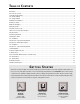
T ABLE OF C ONTENTS Introduction ................................................................................................................................................................ 1 Punch Accessory Pack ................................................................................................................................................. 1 Technical Design Features ......................................................................................................................
INTRODUCTION TO 50 SERIES Rockford Fosgate is distinguished as the global leader in building high performance amplifiers. Since the introduction of the 250m2 and 250m, new performance standards were set for sound quality and flexibility and have risen to an even higher level with the introduction of the 50.2 and 50.1 “competition” amplifiers.
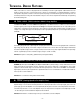
T ECHNICAL D ESIGN F EATURES Many of the solutions to common design problems encountered by Rockford Fosgate engineers created entire new circuit designs as well as new ways to construct the Punch 50.2 and 50.1 Power Amplifiers. In our flagship amplifiers, no expense was spared in design and construction from the unique circuitry design to the manufacturing process that has proven to be the industry reference for many years.
◆ DSM (Discrete Surface Mount Technology) The DSM (Discrete Surface Mount) manufacturing process combines the advantages of both discrete components and integrated circuitry. Rockford Fosgate is the only American amplifier manufacturer to have invested millions into this process. DSM components differ from conventional discrete components in different ways. They are more compact, more rugged, and they efficiently dissipate generated heat.
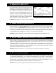
◆ Balanced Line Inputs (50.2) Using the Balanced Line Inputs provides the last word in achievable rejection of noise induced in the cable between the source and the amplifier. The differential input circuitry (Figure 2) used in the balanced input system rejects whatever signals are common to both of the shielded, twisted-pair conductors. Balanced line is universal in concert installations where the stage and mixing consoles are hundreds of feet apart.
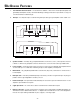
50.2 D E S I G N F E AT U R E S 1. Cast Aluminum Chrome Heatsink – The cast aluminum heatsink of the Punch Power amplifier dissipates heat generated by the amplifier's circuitry. The inherent advantage of casting provides a 30% improvement of cooling over conventional extrusion heatsink designs. 2. End Caps – The unique end caps conceal the wiring and input cables, giving the amplifier a clean “stealth” look. 3 13 8 Unbal. Speaker + L – 0°-180° 6 L (Mono) 7 Gain 10 3 R Bal.
10. Input Sensitivity Controls – The input level controls are preset to match the output of most source units. They can be adjusted to match output levels from a variety of source units. 11. Internal Crossovers – These built-in crossover cards are configurable for a multitude of operating frequencies. The orientation of the card in its socket determines its function of high-pass, low-pass or full range operation. 12.
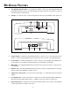
50.1 D E S I G N F E AT U R E S 1. Cast Aluminum Chrome Heatsink – The cast aluminum heatsink of the Punch Power amplifier dissipates heat generated by the amplifier's circuitry. The inherent advantage of casting provides a 30% improvement of cooling over conventional extrusion heatsink designs. 2. End Caps – The unique end caps conceal the wiring and input cables, giving the amplifier a clean “stealth” look.
10. Internal Crossover – This built-in crossover card is configurable for a multitude of operating frequencies. The orientation of the card in its socket determines the function of high-pass, low-pass or full range operation. 11. Phase Switch – This switch enables you to easily invert the phase without having to disconnect the speaker wires. 12. Crossover Switch – This multi-function switch enables you to select a 12dB per octave slope or 24dB per octave slope for the internal crossover.
I NSTALLATION C ONSIDERATIONS Tools Needed The following is a list of tools you will need for installing the “50 Series” Power amplifiers: Allen wrenches 9/64" & 3/32" (included) Wire strippers Battery post wrench Electric hand drill and assorted bits Wire Cutters Voltmeter Wire crimpers Assorted connectors This section focuses on some of the vehicle considerations for installing your new Punch amplifier.
M OUNTING L OCATION S The mounting location and position of your amplifier will have a great effect on its ability to dissipate the heat generated under normal operation. The design of our cast aluminum heatsink serves to easily dissipate the heat generated over a wide range of operating conditions. However, to maximize the performance of your amplifier, care should be taken to ensure adequate ventilation.
WIRING THE SYSTEM CAUTION: Avoid running power wires near the low level input cables, antenna, power leads, sensitive equipment or harnesses. The power wires carry substantial current and could induce noise into the audio system. 1. Configure the internal XCard crossovers prior to installation. Refer to the “Using the Signal Switching Network” (page 19 for the 50.2 and page 31 for 50.1) for further information. 2. Plan the wire routing.
11. After the final inspection is complete, install the power fuse and enjoy listening. During the initial listening period, you may need to “fine tune” any phasing and level settings within your particular vehicle. To aid in this procedure, play a track with high musical content and cruise around your neighborhood.
TABLE OF CROSSOVER COMPONENT VALUES L a d v a n c e d C 6dB/Octave Low-Pass 6dB/Octave High-Pass Speaker Impedance Freq. Hertz 2 OHMS 8 OHMS 4 OHMS L C L 80 100 130 4.1mH 3.1mH 2.4mH 1000µF 800µF 600µF 8.2mH 6.2mH 4.7mH 200 260 400 1.6mH 1.2mH .8mH 400µF 300µF 200µF 600 800 1000 .5mH .41mH .31mH 1200 1800 4000 6000 9000 12000 C L C 500µF 400µF 300µF 16mH 12mH 10mH 250µF 200µF 150µF 3.3mH 2.4mH 1.6mH 200µF 150µF 100µF 6.8mH 4.7mH 3.3mH 100µF 75µF 50µF 136µF 100µF 78µF 1.
U SING THE XCARD The crossover functions are controlled through the use of an XCard and can be set for high-pass, low-pass or full range operation. The XCard shipped with your amplifier is set for Full Range. Each crossover card has two faces: one face operates Full Range, the other has arrows to indicate the edge for selecting HP (high-pass) or LP (low-pass) operation. Orient the card with the desired operating edge, indicated by the arrow, toward the socket terminals inside the amplifier.
XC ARD R ESISTOR C HART a d v a n c e d Our tests have shown that using 0.047mf capacitors for frequencies below 100Hz, and 0.022mf capacitors for frequencies above 100Hz, result in more linear crossover control. Refer to the Specifications page to determine the capacitor value of each supplied XCard. Butterworth Alignment Q = .707 Butterworth Alignment Q = .707 1% resistors used with 0.022mF capacitors 1% resistors used with 0.
50.2 I NSTALLATION ® 50.2 Power Connections (Option #1) Power REM Dual B+ Dual GND Connect to remote turn-on lead of source unit. Connect to chassis ground of vehicle* Less than 18" + – Connect to B+ of battery with a 40 amp fuse. *Keep wire as short as possible. 50.2 Power Connections (Option #2) Power Dual B+ Dual GND Connect to remote turn-on lead of source unit. Less than 18" + – Connect to B+ of battery with a 40 amp fuse. *Keep wire as short as possible.
® RCA Input Stereo Operation Unbal. Speaker + L – 0°-180° L (Mono) R Bal. Pass Thru Gain Bal. Input L EZ-180°-0° Bridged R Gain – – 1Ω Min. 1Ω Min.
® Bridged Operation RCA Input Unbal. Speaker + L – 0°-180° L (Mono) R Bal. Bal. Input Pass Thru Gain + Speaker Terminal L EZ-180°-0° Bridged R Speaker – R + Gain + – Speaker Terminal – 2Ω min.
U S I N G T H E 50.2 SIGNAL S W I T C H I N G N E T W O R K ® ® I N S T A L L A T I O N The Punch 50.2 Power amplifier has a crossover switching network which enables you to: • • • • • “Audiophile Bypass” the 50.2 and Pass-Thru Configure a 12dB per octave filter for both 50.2 and Pass-Thru “Audiophile Bypass” the 50.2 and configure a 12dB per octave filter for the Pass-Thru Configure a 24dB per octave filter for the 50.
® “Audiophile Bypass” as it affects the output of the 50.2 and Pass-Thru. XCard not required. XCard 1 XCard 2 R AUD VOL PWR CLOCK DISC AMFM ST ® Ch LD RDM RPT AUTO DSPL SEL ILLUM P.SCN LOUD D.SCN SCAN RPT RDM DIM PAUSE 1 2 3 4 5 6 TUNE ® Unbal. Speaker + L – 0°-180° Gain L (Mono) R Bal. Pass Thru Bal. Input L R EZ-180°-0 ° Bridged Speaker – R + Gain + + Full Range – 20Hz Full Range 20kHz + – 20Hz Full Range 20Hz 20kHz • 50.
® Configure a 12dB per octave filter for both the 50.2 and Pass-Thru. 250x22 XCard* Pass Thru XCard* HP LP R AUD VOL PWR DISC AMFM ® ST Ch LD RDM RPT CLOCK AUTO DSPL P.SCN SEL ILLUM LOUD D.SCN SCAN RPT RDM DIM PAUSE 1 2 3 4 5 6 XCard 1 TUNE XCard 2 ® Unbal. Speaker + L – 0°-180° L (Mono) R Bal. Pass Thru Gain Bal.
® “Audiophile Bypass” the 50.2 and configure a 12dB per octave filter for the Pass-Thru. Pass Thru XCard XCard not required. LP R AUD VOL PWR DISC AMFM ® ST Ch LD RDM RPT CLOCK AUTO ILLUM DSPL P.SCN LOUD SEL D.SCN SCAN RPT RDM DIM PAUSE 1 2 3 4 5 6 TUNE XCard 1 XCard 2 ® Unbal. Speaker + L – 0°-180° Gain L (Mono) R Bal. Pass Thru Bal.
– 23 – – + ST ® Ch LD RDM RPT 2 1 AUTO 3 RPT P.SCN Speaker + L – SCAN DSPL CLOCK D.SCN ILLUM LOUD 5 DIM SEL XCard 1 XCard 2 HP HP + R Full Range L L (Mono) R Pass Thru R 20Hz 250x 2 2 XCard* Gain TUNE Bal. Unbal. 6 PAUSE 0°-180° 4 RDM 250x 2 2 XCard* 20kHz 24dB/Octave High-Pass ® DISC AMFM 20Hz PWR AUD *Note: Both XCard inserted as HP or LP. VOL 20kHz – Bal. Input – + VOL – + PWR AUD ST ® Ch LD RDM RPT 2 AUTO 3 RPT P.
USING THE 50.2 BALANCED LINE INPUTS The Balanced Line Inputs can be utilized with the optional Balanced Line Transmitter. Unlike standard RCA cables that use two wires to carry the audio signal and ground, balanced lines use three. In a balanced line, the output signal and its inverted replica travel down a pair of wires where the ground connects via the shield. As the amplifier receives the signals, it cancels out whatever signals are common to both wires.
Level Setting the BLT a d v a n c e d O p e r a t i o n R AUD VOL PWR DISC AMFM ® ST Ch LD RDM RPT CLOCK AUTO DSPL P.SCN SEL ILLUM LOUD D.SCN SCAN RPT RDM DIM PAUSE 1 2 3 4 5 6 TUNE ® 1kHz Test Tone @ “0dB” 9.3 VAC ® ® BALANCED LINE TRANSMITTER L + • • • • • • • • – R L R Disconnect Speaker(s) from the 50.
50.1 INSTALLATION ® 50.1 Power Connections (Option #1) REM Dual B+ Dual GND Connect to remote turn-on lead of source unit. Connect to chassis ground of vehicle* Less than 18" + – Connect to B+ of battery with a 40 amp fuse. *Keep ground connections as close to each other as possible. 50.1 Power Connections (Option #2) Dual B+ Dual GND Connect to remote turn-on lead of source unit. Less than 18" + 1 farad • 20 VDC • 95°C cap 1.
Mono Operation ® RCA Input L (Mono) R Power Speaker – + Gain L Pass Thru R Pass Thru – L + R / L (Mono) RCA Inputs + 1Ω minimum • Signal Input Switch set to L+R for RCA input • Phase Switch set to 0° • Impedance should be 1Ω minimum • XCard can be set for High-Pass, Low-Pass or Full Range X-Over 0°-180° 24dB/12dB/0dB – 27 – ® I N S T A L L A T I O N
• • • • + – Speaker – + Gain L Pass Thru R Pass Thru L (Mono) R X-Over 0°-180° 24dB/12dB/0dB L + R / L (Mono) RCA Inputs Power Signal Input Switch (50.1 #1 / #2) set to L(Mono) for single RCA input) Phase Switch (50.1 #1/2) set to 0° Impedance for each amplifier should be 1Ω minimum XCard for each amplifier can be set for High-Pass, Low-Pass or Full Range 1Ω minimum 50.1 #1 L RCA Input Stereo Operation using two Punch 50.1 Power Amplifiers R 1Ω minimum + – 50.
– Phase Switch (50.1 #2) set to 180° All speaker polarity on right amplifier is inverted to correct for signal phase Gain (50.1 #1/#2) set equally to balance the subwoofer Impedance for each stereo channel should be 1Ω minimum Impedance for bridged channel should be 2Ω minimum XCard (50.1 #1/#2) set to Full Range Passive crossovers are needed for proper stereo/mono operation • • • • • • • 2Ω minimum low frequency + Phase Switch (50.
Speaker – + Gain Phase Switch (50.1 #1) set to 0° Phase Switch (50.1 #2) set to 180° Gain (50.1#1/#2) set equally to balance the subwoofer Impedance for bridged channel should be 2Ω minimum XCard (50.1 #1/#2) set to identically as High-Pass, Low-Pass or Full Range • • • • – • 2Ω minimum + X-Over 0°-180° 24dB/12dB/0dB L + R / L (Mono) RCA Inputs Power Signal Input Switch (50.1 #1/#2) set to L+R for RCA input L Pass Thru R Pass Thru L (Mono) R • + Speaker Terminal 50.
U S I N G T H E 50.1 S IGNAL SWITCHING NETWORK ® “Audiophile Bypass” the 50.1 XCard not required. R AUD VOL PWR DISC AMFM ST ® Ch LD RDM RPT CLOCK AUTO DSPL P.SCN SEL ILLUM LOUD D.SCN SCAN RPT RDM DIM PAUSE 1 2 3 4 5 6 TUNE XCard ® L (Mono) R Power Speaker – + X-Over 0°-180° 24dB/12dB/0dB Gain L Pass Thru R Pass Thru L + R / L (Mono) RCA Inputs – + Full Range Full Range 20Hz 20kHz + 20Hz – 20kHz • Xover is set to 0dB • The 50.
® Configure a 12dB per octave filter for the 50.1 LP R AUD VOL PWR DISC AMFM ST ® Ch LD RDM RPT CLOCK AUTO DSPL P.SCN SEL ILLUM LOUD D.
Configure a 24dB per octave filter for the 50.1 ® LP R AUD VOL PWR DISC AMFM ® ST Ch LD RDM RPT CLOCK AUTO DSPL P.SCN SEL ILLUM LOUD D.
S YSTEM D IAGRAMS 100 Watt System (rated @ 4 ohms) Total Power Delivery (RMS) Tweeters 100 Watts Midrange 100 Watts Woofers 200 Watts R AUD VOL PWR DISC AMFM ® ST Ch LD RDM RPT SEL CLOCK AUTO ILLUM DSPL P.SCN LOUD D.SCN SCAN RPT RDM DIM PAUSE 1 2 3 4 5 6 TUNE ® Pass-Thru 80Hz HP 80Hz HP 50.
– 35 – ST ® 4Ω Ch LD RDM RPT 2 1 AUTO 3 RPT P.SCN 50.1 Rear SCAN D.SCN DSPL CLOCK 4 RDM ILLUM LOUD 5 DIM 6 PAUSE TUNE R Front Right XCard 80Hz LP SEL 50.2 (bridged amp) 80Hz HP 80Hz HP 24dB/octave HP PWR-54 4Ω TX-4183 80Hz-20kHz PWR-14X PWR-14X TX-4183 20Hz-80Hz 24dB/octave LP PWR-410 4Ω 4Ω 4Ω PWR-54 4Ω PWR-14X PWR-14X 24dB/octave HP 80Hz-20kHz TX-4183 TX-4183 3kHz-20kHz 50.
– 36 – 50.1 P/T* ST ® 50.1 Ch LD RDM RPT AUTO 3 RPT P.SCN Rear 2 SCAN P/T* 1 D.SCN DSPL CLOCK 4 RDM ILLUM LOUD 5 DIM 6 PAUSE 50.1 SEL R P/T* TUNE 4Ω Front Right 50.1 50.2 (bridged amp) 80Hz HP 80Hz HP *P/T (Pass-Thru) is used to daisy-chain amplifiers.
500 Watt System (rated @ 4 ohms) Total Power Delivery (RMS) Tweeters 400 Watts Midrange 400 Watts Midbass 400 Watts Woofers 800 Watts R AUD VOL PWR DISC AMFM ® ST Ch LD RDM RPT CLOCK AUTO DSPL P.SCN SEL ILLUM LOUD D.SCN SCAN RPT RDM DIM PAUSE 1 2 3 4 5 6 TUNE ® Front Right Front Left P/T* P/T* 50.2 50.2 3kHz-20kHz 3kHz-20kHz 24dB/octave HP 24dB/octave HP 3k HP 3k HP 3k HP 3k HP 4Ω 4Ω PWR-14X PWR-14X 400Hz HP 400Hz HP 3k LP 3k LP 50.2 50.
ROCKFORD FOSGATE ACCESSORIES Balanced Line Transmitter (FG-BLT) ® The Balanced Line Transmitter converts signal RCA cables from the source unit to balanced signals. The BLT improves sound quality in the system by eliminating noises generated by vehicle electrical systems. The BLT is available for Rockford Fosgate products that offer a balanced input. R AUD VOL DISC AMFM PWR ® ST Ch LD RDM RPT CLOCK AUTO ILLUM DSPL P.SCN LOUD SEL D.
Energy Storage Capacitors ® Energy Storage Capacitors are used to provide extra current needed by amplifiers to reproduce musical transients. The capacitors also have the natural ability to filter AC ripple caused by the alternator, reducing the chance of noise in the system. The capacitors are available in a variety of values and will maximize both the sound quality and performance that Rockford Fosgate amplifiers can deliver. Power REM Dual B+ Dual GND Battery + ® ® the connecting ® 1.
T ROUBLESHOOTING Symptom Amplifier does not turn on. (Power LED is off) Amplifier has no sound. (Power LED is on) TROUBLE-S H O O T I N G Diagnosis Remedy Voltage applied to the REM terminal of the amplifier is not between 10.5 and 15.5 volts or there is no voltage present. Check the alternator, battery, fuse, and wiring and repair as necessary. If the voltage is above 15.5 volts, have the electrical system inspected by an authorized car service center.
Symptom Speaker Output Low or Distorted Amplifier Noise (Turn-on Pop) No output from Pass-Thru output of amplifier. Diagnosis Remedy TROUBLE-S H O O T I N G Input gain(s) for amplifier incorrectly set. Readjust input gains of amplifier. Source unit output too low or source unit has no output. Check system with known working source and repair or replace original source as needed. Phase selection of amplifier incorrectly selected or speakers wired out of polarity from the left to right channel.
Symptom Low or distorted output from the Pass-Thru output of the amplifier. Diagnosis Remedy TROUBLE-S H O O T I N G Input gain(s) for amplifier incorrectly set. Readjust input gains of amplifier. Source unit output too low. Check system with known working source and repair or replace original source as needed. XCards are missing or not placed properly in crossover slots and/or switches are not properly selected. Check crossover switches and XCard positions and repair or replace as necessary.
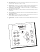
AUTOSOUND 2000's QUICK CHECK FOR TROUBLESHOOTING CAR AUDIO SYSTEMS Preface: All audio systems exhibit noise; however, if the level of noise is low enough, and the signal level high enough, noise should not be a problem. This means that it is very important that the signal level throughout the system be optimized BEFORE dealing with your noise problem.
B. If the deck is quiet, then congratulations, you're on your way to a successful installation. It is now time to slowly, methodically, reinstall the deck back into its final position. Test for noise each step of the way. If the noise returns, suspect the signal cables. Forget shielding because it will have only a very, minimal effect within the audio band. We highly suggest using twisted pair cables or a balanced transmission system for cable induced noise.
D YNAMIC P OWER M EASUREMENTS About the Dynamic Power Measurements The Audio Graph PowerCube is a test instrument used to measure the output of an amplifier in accordance with IHF-202 industry standards. The IHF-202 standard is a dynamic power measurement and was developed as a means of measuring power in a manner that best represents the Real World operation of an amplifier. Many manufacturers, including Rockford Fosgate, at times will measure amplifier power into a fixed resistor (4 ohm, 2 ohm).
50.2 S PECIFICATIONS Dynamic Power Rating (IHF-202 Standard) - Measured at 14.4V Per channel into a 4Ω load Per channel into a 2Ω load Per channel into a 1Ω load 2-channel bridged into a 2Ω load 50 Watts 90 Watts 150 Watts 300 Watts Continuous Power Rating (Competition Standard) - Measured at 13.8 Battery Volts RMS continuous power per channel, all channels driven into a 4Ω load from 20 to 20,000Hz with less than 0.
.1 S PECIFICATIONS Dynamic Power Rating (IHF-202 Standard) - Measured at 14.4V Mono into a 4Ω load Mono into a 2Ω load Mono into a 1Ω load 2-channel Bridged (using 2 Punch 50.1) into a 2Ω load 100 Watts 200 Watts 325 Watts 650 Watts Continuous Power Rating (Competition Standard) – Measured at 13.8 Volts RMS continuous power mono, into a 4Ω load from 20-20,000Hz with less than 0.05% THD 50 Watts RMS continuous power mono, into a 2Ω load from 20-20,000Hz with less than 0.
LIMITED W ARRANTY I NFORMATION Rockford Corporation offers a limited warranty on Rockford Fosgate products on the following terms: • Length of Warranty 3 years on electronics 2 years on source units 90 days on electronic B-stock (receipt required) 30 days on speaker B-stock (receipt required) • What is Covered This warranty applies only to Rockford Fosgate products sold to consumers by Authorized Rockford Fosgate Dealers in the United States of America or its possessions.
A N A M T R T R IO E IO O T N F N IN A L IN – 49 –
LEA DETENIDAMENTE LAS SIGUIENTES INSTRUCCIONES DE INSTALACIÓN DEL PRODUCTO. EVITARA POSIBLES DAÑOS A VD., AL VEHÍCULO O AL PRODUCTO. INTRODUCCIÓN Rockford Fosgate se distingue como el lider indiscutible en la construccion de amplificadores de altas prestaciones. Desde la introduccion de los modelos 250m2 y 500m se han fijado nuevos standards en calidad de sonido y flexibilidad que ahord han sido superados con los amplificadores de “competicion” 50.2 y 50.1.
ESPAÑOL Operación mono/estéreo RCA Input Unbal. Speaker + L – 0°-180° Gain L (Mono) R Bal. Pass Thru Bal. Input L EZ-180°-0° Bridged R Gain – + 1Ω min. 1Ω min. + + Speaker Terminal Speaker – R + – + – – Speaker Terminal 2Ω min.
ATTENTION: Veuillez lire les instructions suivants pour l'nstallation de ce produit. Ne pas les suivre pourrait causer des blessures ou endommager le véhicule. INTRODUCTION Rockford Fosgate se distingue en étant le leader mondial de la fabrication d'amplificateurs de haute puissance. Depuis l'introduction du 250m2 et du 500m, de nouvelles normes en matière de qualité sonore et de flexibilité ont été fixées. Avec l'introduction des modèles “competition” 50.2 et 50.1, ces normes seront à nouveau améliorées.
Opération stéréo/mono (Tri-mode) RCA Input Unbal. Speaker + L – 0°-180° Gain L (Mono) R Bal. Pass Thru Bal. Input L EZ-180°-0° Bridged R Gain – + 1Ω min. 1Ω min. + + Speaker Terminal Speaker – R + – + – – Speaker Terminal 2Ω min.
Bitte lesen Sie diese Gebrauchsanleitung zuerst sorgfältig durch. Das kann Sie vor dem falschen Einsatz, Ausfallen oder sogar Beschädigung des Produktes oder Ihres Fahrzeuges schützen. EINLEITUNG Rockford Fosgate ist bekannt als einer der weltweit führenden Hersteller von “high performance” Auto-HiFi Versstärkern. Spätestens seit der Vorstellung der 250m2 and 500m haben wir neue Maβstäbe für hervorragende Klangqualität und mehr Flexibilität gesetzt.
Stereo/Mono Betrieb RCA Input Unbal. Speaker + L – 0°-180° Gain L (Mono) R Bal. Pass Thru Bal. Input L EZ-180°-0° Bridged R Gain – + 1Ω min. 1Ω min. + + Speaker Terminal Speaker – R + – + – – Speaker Terminal 2Ω min.
PREGO LEGGERE LE SEGUENTI ISTRUZIONI PER L'INSTALLAZIONE DI QUESTO PRODOTTO, IL NON SEGUIRLE POTREBBE RISULTARE SERIAMENTE DANNOSO PER LA PERSONA O PER IL VEICOLO. INTRODUZIONE Rockford Fosgate é conosciuta per essere il leader indiscusso nella realizzazione di amplificatori ad elevatissime prestazioni. Con l'introduzione dei modelli 250m2 e del 500m Rockford ha stabilito dei nuovi standard di mercato per qualitá timbrica e versatilltá. Con l'introduzione dei modelli “competizione” 50.2 e 50.
Stereo/Mono Operation RCA Input Unbal. Speaker + L – 0°-180° Gain L (Mono) R Bal. Pass Thru Bal. Input L EZ-180°-0° Bridged R Gain – + 1Ω min. 1Ω min. + + Speaker Terminal Speaker – R + – + – – Speaker Terminal 2Ω min. • RCA inputs non sono collegati ad entrambi, i canli destro e sinistro • Interruttore di segnale input selezionato per il non bilanciamento per l'input RCA • Fase sinistra dell'interruttore posizionata su 0°.
MADE IN THE USA This product is designed, developed and assembled in the USA by a dedicated group of American workers. The majority of the components used in the construction of this product are produced by American companies. However, due to the global nature of their manufacturing facilities and the loudspeaker parts industry in general, some parts may be manufactured in other countries. Rockford Fosgate MAN-1528-B 10/97 Rockford Corporation 546 South Rockford Drive Tempe, Arizona 85281 U.S.A. In U.S.