DSM 2-CHANNEL A M P L I F I E R OWNER'S MANUAL ® ®
Dear Customer, Congratulations on your purchase of the world's finest brand of car audio amplifiers. At Rockford Fosgate we are committed to musical reproduction at its best, and we are pleased you chose our product. Through years of engineering expertise, hand craftsmanship and critical testing procedures, we have created a wide range of products that reproduce music with all the clarity and richness you deserve.
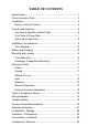
TABLE OF CONTENTS Specifications ................................................................................... 1 Punch Accessory Pack .................................................................... 3 Introduction ...................................................................................... 4 Notes on Internal Circuitry ........................................................... 4 Controls and Features ......................................................................
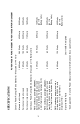
1 40 Watts Per channel into a 4Ω Load 80 Watts 130 Watts 80 Watts 40 Watts 20 Watts 200 Watts 100 Watts 50 Watts Over 110dB A-weighted 120 Watts 60 Watts 30 Watts 110 Watts 200 Watts 420 Watts See Appendix A - Dynamic Power Measurements for information on these specifications. 1 Signal-to-Noise Ratio RMS continuous power mono into a 4Ω load from 20 to 20,000 Hz, with less than 0.
2 Input Impedance Equalization ATC ATC ATC 40 Amps Specifications subject to change without notice. ≤ 20k ohms Bass: +18dB Maximum at 45Hz Treble: +12dB Maximum at 20kHz 30 Amps 20 Amps AGU 50 Amps Internal analog-computer output protection circuitry limits power in case of overload. Thermal switch shuts down the amplifier in case of overheating. Protection Battery Fusing Rates (External to Amplifier) Fuse Type Variable from 40dB to 14dB (250mV - 1 Volt) 25dB 26.
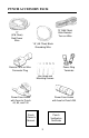
PUNCH ACCESSORY PACK 12' (365.76cm) Blue Remote Turn-on Wire 17' (518.16cm) Red Power Wire 1.5' (45.
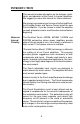
INTRODUCTION This manual provides information on the features, installation, and operation of the Punch 2-channel Amplifiers. We suggest you save this manual for future reference. We strongly recommend you have your Authorized Rockford Fosgate Dealer and Service Center install the new Punch amplifier. If you do choose to install the amplifier yourself, please be sure to read the entire manual before beginning.
High powered audio amplifiers must always address the problem of power device reliability. In particular, load fault conditions can easily destroy an amplifier that is not carefully designed. Rockford Fosgate has answered this problem with the development of Real Time Power Protection (RTPP). The RTPP circuits protect the Punch amplifiers by multiplying output device voltage and current values to obtain approximate instantaneous device power.
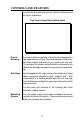
CONTROLS AND FEATURES This section describes the various controls and features of the Punch amplifiers. Top View of Amplifier and End Caps Punch Housing The cast aluminum heatsink of the Punch is designed for high performance cooling. The raised design of the housing allows cables and wires to run underneath the unit. This provides for greater wiring flexibility and protects the cables from damage caused by excessive heat and bending.
Front View of Power Side REM Connector REM Connector LED Indicator B+/GND Connector The Punch is turned on by connecting the blue remote turn-on wire to the source unit’s “Accessory” or “Auto Antenna” lead, either of which will go to +12 volts when the source unit is turned on. LED Power The LED illuminates red when the unit is turned on. Indicator B+/GND Power Connector These connectors are used to supply power and ground to the amplifier and accept 12 AWG - 8 AWG wires.
Front View of Input/Output Terminals Treble Adjust Left Speaker Output Left Input Gain Control Right Input Gain Control RCA Input Connectors Bass Adjust Right Speaker Output Speaker Output Terminals These gold plated terminal blocks connect the Right and Left channel outputs to the speakers and accept wire sizes from 8 gauge through 18 gauge. Gold plated connectors are immune to corrosion that can cause signal deterioration.
INSTALLATION CONSIDERATIONS This section focuses on some of the vehicle considerations for installing your new Punch amplifier. Checking your battery and current sound system, as well as preplanning your system layout and best wiring routes will save installation time. When deciding how to lay out your new system, be sure that each component will be easily accessible for making adjustments. Before beginning any installation, be sure to follow these simple rules: 1.
connected to metal that is welded to the main body, or chassis, of the vehicle. Tools Needed The following is a list of tools you will need for installing the Punch amplifier: Allen Wrenches (7/64" & 3/32") Wire Strippers Battery Post Wrench Electric Hand Drill with assorted bits Voltmeter Wire Crimpers (i.e., Perfect Interface RT-KT1) BATTERY AND CHARGING Punch amplifiers will naturally put an extra load on your battery and charging system.
Passenger Compartment Mounting Under the seat or floor mounting will work as long as there is a minimum of 1” (2.5cm) of air gap above the amplifer's heatsink. Vertical mounting is still the best, and under dash mounting is satisfactory as well. WIRING THE PUNCH Caution! Be sure to avoid running the power wires near the input cabling antenna, power leads, sensitive equipment or harnesses. The power wires carry substantial currents and can induce noise.
4. Cover the crimped area with the protective boot that is supplied with the fuse holder. 5. Repeat the above steps to connect the remainder of the red power wire to the other side of the fuse holder and route to the amplifier mounting location. Wiring the Power Connectors 1. Strip back approximately 3/8" (.95cm) of wire. 3/8" (.95cm) 2. Insert the bared wire into the connector and crimp in place as shown in the following diagram.
Ground The GND terminal grounds the amplifier and is connected to the chassis of the vehicle with 12 gauge, or heavier, stranded wire. To prevent ground loops, we recommend you refrain from extending the ground wire beyond 18" (45.72cm) in any installation. The ends of the Power and Ground wires that are connected to the amplifier should be stripped back 5/8” (1.59cm). Remote Turn-on The Punch amplifiers are turned on by supplying positive (+) 12 volts to the REM terminal.
Mono Configuration The Punch amplifiers are capable of bridged mono configurations. This configuration enables you to: • Run a single woofer in a stereo system • Run two bridged amplifiers as a high power stereo system • Run one amplifier with a bridged mono woofer and another as a high-frequency stereo amp, etc. For more information refer to the wiring diagrams beginning on page 17. Caution! Punch amplifiers are not recommended for impedance loads below 2Ω stereo or 4Ω bridged.
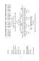
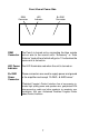
High and low pass filter sections have a cutoff rate that increases as the number of components in the filter increases. This means that a complex filter with a number of parts will stop the unwanted frequencies faster than a simple filter. The amount of reduction is measured in dB per octave. The most common filters used in speaker crossovers, as stated above, are 6 dB per octave which uses one component per filter.
C L 6 dB/Octave Low Pass 6 dB/Octave High Pass Speaker Impedance Freq. Hertz 2 OHMS 8 OHMS 4 OHMS L C L 80 100 130 4.1mH 3.1mH 2.4mH 1000µF 800µF 600µF 8.2mH 6.2mH 4.7mH 200 260 400 1.6mH 1.2mH .8mH 400µF 300µF 200µF 600 800 1000 .5mH .41mH .31mH 1200 1800 4000 6000 9000 12000 C L C 500µF 400µF 300µF 16mH 12mH 10mH 250µF 200µF 150µF 3.3mH 2.4mH 1.6mH 200µF 150µF 100µF 6.8mH 4.7mH 3.3mH 100µF 75µF 50µF 136µF 100µF 78µF 1.0mH .82mH .62mH 68µF 50µF 39µF 2.0mH 1.6mH 1.
SAMPLE WIRING DIAGRAMS BRIDGED WOOFERS B+ GND L +OUT– TREBLE GAIN IN IN GAIN BASS +OUT– R SOURCE UNIT + – – 8 OHM + 8 OHM 17
– 4 OHM + + + TX 8 OHM 4 OHM – – TX MBX – 8 OHM 4 OHM – MX MX + + B+ GND SOURCE UNIT L +OUT– TREBLE GAIN IN IN GAIN BASS +OUT– R + – – + – + – + 4 OHM – 3-WAY SYSTEM 18 8 OHM 4 OHM 4 OHM 8 OHM +
B+ GND – + L +OUT– TREBLE GAIN IN + Left IN GAIN BASS +OUT– – Left + Right C-400, TT-2.5 R – Right – C-400, TT-2.5 + + + 5.25" 4 OHM MID-BASS SP-54 – – Bridged Mono + MX124 SP-44 – TX124 + SPT-14RX – MX124 4" 4 OHM MIDRANGE SP-44 TX124 1" DOME W/CROSSOVER 4 OHM + SPT-14RX C-200, TT-3.5 + 5.25" 8 OHM MID-BASS SP-58 SP-58 – + – MX124 SP-48 – + – – C-200, TT-3.
TROUBLESHOOTING Problem Connecting end caps when using large gauge wire. Solution Cut the wire casing on the diagonal as shown in the following diagram. Insert the wire into the connector. Twist the wire around so that the long end of the insulation faces up. Bend the wire prior to tightening in place. INSULATION STRIP WIRE > < 5/8" > > AMP > Note: For easier assembly, only 5/8" (1.89cm) of wire should be bared.
Problem Amplifier will not play – Remote turn-on light is off. Solution 1. Check the DC voltage at the amplifier's B+ terminal with a voltmeter. The voltage should measure between 11.5V - 15.5V. If voltage is not found, check the battery, fuse, fuse housing and wire connections. Fix, repair, or replace accordingly. 2. Check the voltage at the amplifier's remote turn-on lead. The voltage should measure between 11V - 15V. a.
Problem Amplifier gets too hot. Solution 1. Be sure the amplifier is properly mounted. You should be able to place your hand a few inches above the amplifier housing and feel the heat rising when the unit is on. 2. Be sure the amplifier is properly vented. An ideal situation is to have the air flow through the heatsink fins. Hot air rises, so mount the heatsink by aligning the fins vertically. This allows the air to flow freely, carrying away the heat.
switch from the clean power source. Problem Engine Noise (Whine) Solution 1. Disconnect the speakers from the amplifier. Connect a test speaker to the amplifier output terminals. If the noise goes away, check your speaker leads, speakers and crossovers. 2. Use a "shorting plug" to mute the input signal at the amplifier. If the noise goes away: a. Bypass all of the other equipment (i.e., crossovers and equalizers) and connect the head unit directly to the amp.
DYNAMIC POWER MEASUREMENTS About the Dynamic Power Measurements The Audio Graph PowerCube is a test instrument used to measure the output of an amplifier in accordance with IHF-202 industry standards. The IHF-202 standard is a Dynamic power measurement and was developed as a means of measuring power in a manner that best represents the Real World operation of an amplifier. Many manufacturers, including Rockford Fosgate, at times will measure amplifier power into a fixed resistor (4 ohm, 2 ohm).
A 4 ohm speaker may experience a drop in impedance 46 times lower than its nominal (printed) impedance. A speaker will also create phase shifts in the signal that is passed through it. These phase shifts happen because a speaker is an inductor (voice coil) and a capacitor (compliance of the surround/spider), as well as a resistor (voice coil wire). To simulate a speaker the Audio Graph PowerCube measures output power into 20 different loads. It tests at 8 ohms, 4 ohms, 2 ohms and 1 ohm.
What is an Amplifier? An amplifier by definition is a voltage generating device, recreating the signal which is input to it identically but with increased volume. It will be connected to a reactive load (the speaker). The impedance of this load and phase of the signal passing through the load will vary, dependent upon the frequency of the input signal (music).
WARRANTY INFORMATION Rockford Fosgate warrants all electronics to the original consumer/purchaser to be free from defects in materials or workmanship for a period of three (3) years. We will cover parts and labor provided the product was purchased from an Authorized Rockford Fosgate Dealer. This warranty does not apply to any product on which the seals and/or serial number have been broken, removed, tampered with, defaced or altered in any manner.
Rockford Fosgate A Division of Rockford Corporation 546 South Rockford Drive Tempe, Arizona 85281 U.S.A. In U.S.A., (602) 967-3565 In Canada, call Korbon (905) 567-1929 In Europe, Fax (49) 4207-801250 REV.