bd1000P bd1500P Installation & Operation Mono Amplifiers Installation et fonctionnement Instalación y funcionamiento Einbau und Betrieb Installazione e funzionamento
INTRODUCTION Dear Customer, Congratulations on your purchase of the world's finest brand of car audio amplifiers. At Rockford Fosgate we are fanatics about musical reproduction at its best, and we are pleased you chose our product. Through years of engineering expertise, hand craftsmanship and critical testing procedures, we have created a wide range of products that reproduce music with all the clarity and richness you deserve.
GETTING STARTED Welcome to Rockford Fosgate! This manual is designed to provide information for the owner, salesperson and installer. For those of you who want quick information on how to install this product, please turn to the Installation Section of this manual. Other information can be located by using the Table of Contents. We, at Rockford Fosgate, have worked very hard to make sure all the information in this manual is current.
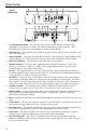
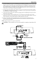
DESIGN FEATURES Power Connection 1. Cast Aluminum Heatsink – The cast aluminum heatsink of the amplifier dissipates heat generated by the amplifier's circuitry. The inherent advantage of casting provides a 30% improvement of cooling over conventional extrusion heatsink designs. 2. REM Terminal – This spade terminal is used to remotely turn-on and turn-off the amplifier when +12V DC is applied. 3.
INSTALLATION INSTALLATION CONSIDERATIONS The following is a list of tools needed for installation: Volt/Ohm Meter Wire strippers Wire crimpers Wire cutters #2 Phillips screwdriver Battery post wrench Hand held drill w/assorted bits 1/8" diameter heatshrink tubing Assorted connectors Adequate Length—Red Power Wire Adequate Length—Remote Turn-on Wire Adequate Length—Black Grounding Wire This section focuses on some of the vehicle considerations for installing your new Amplifier.
INSTALLATION Trunk Mounting Mounting the amplifier vertically will provide the best cooling of the amplifier. Mounting the amplifier on the floor of the trunk will work but provides less cooling capability than vertical mounting. Mounting the amplifier upside down to the rear deck of the trunk will not provide proper cooling and will severely affect the performance of the amplifier and is strongly not recommended.
INSTALLATION 6. Prepare the REM turn-on wire for connection to the amplifier by stripping 1/2" of insulation from the wire end. Insert the bared wire into the REM terminal and tighten the set screw to secure the cable into place. Connect the other end of the REM wire to a switched 12 volt positive source. The switched voltage is usually taken from the source unit's accessory lead.
INSTALLATION REMOTE PUNCH BASS Mounting and installation 1. Find a location, either under the dash or near the center console, that gives easy access to the remote. Mounting Clip 2. Using the screws supplied, install the mounting clip with the tabs towards t he back. 3. Route the cable for the remote and connect to both the remote and amplifed subwoofer. 4. Slip the remote onto the mounting clip until it snaps into place. 5. Install the decal and knob onto the remote.
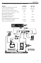
APPLICATIONS RECOMMENDED CONFIGURATION FOR 0NE (1) AMPLIFIER MODEL bd1000P bd1500P Operational Voltage Range (DC Volts) 10 – 15.5 10 – 15.
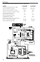
APPLICATIONS RECOMMENDED CONFIGURATION FOR TWO (2) AMPLIFIERS MODEL Operational Voltage Range (DC Volts) Minimum Speaker Impedance (2) bd1000P (2) bd1500P 10 – 15.5 10 – 15.
TROUBLESHOOTING NOTE: If you are having problems after installation follow the Troubleshooting procedures below. Procedure 1: Check Amplifier for proper connections. Verify that POWER light is on. If POWER light is on skip to Step 2, if not continue. 1. Check in-line fuse on battery positive cable. Replace if necessary. 2. Verify that Ground connection is connected to clean metal of the vehicle’s chassis. Repair/replace if necessary. 3. Verify there is 10.5 - 15.
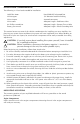
SPECIFICATIONS MODEL- PRO bd1000P bd1500P Continuous Power Rating (RMS) - Measured at 14.4 Battery Volts 4Ω Load Mono 500 Watts x 1 750 Watts x 1 2Ω Load Mono 1000 Watts x 1 1500 Watts x 1 Dimensions: (with Endbell) Height Width Length 2.4" (6.1cm) 9.8" (24.89cm) 13.35" (33.96cm) 2.4" (6.1cm) 9.8" (24.89cm) 18.35" (46.
LIMITED WARRANTY INFORMATION Rockford Corporation offers a limited warranty on Rockford Fosgate products on the following terms: Length of Warranty PUNCH Amplifiers – 2 years All Other Amplifier Models – 3 years Source Units – 1 year Speakers – 1 year 90 days on speaker, amplifier and source unit B-stock (receipt required) What is Covered This warranty applies only to Rockford Fosgate products sold to consumers by Authorized Rockford Fosgate Dealers in the United States of America or its possessions.
INTRODUCCIÓN Estimado cliente, Español Felicitaciones por su compra de la mejor marca del mundo de amplificadores para automóviles. En Rockford Fosgate somos fanáticos de la mejor reproducción musical y estamos agradecidos de que haya escogido nuestro producto. Con muchos años de experiencia en ingeniería, conocimiento del oficio y procedimientos de prueba críticos, hemos creado una amplia gama de productos para reproducción musical con toda la claridad y la riqueza que usted merece.
INICIO ¡Bienvenidos a Rockford Fosgate! Este manual ha sido creado para proporcionarle información al dueño, vendedor y técnico de instalación. Para quienes desean información rápida sobre cómo instalar este producto, por favor vean la Sección Instalación de este manual. El resto de la información puede encontrarse usando el Índice de Materias. Nosotros, en Rockford Fosgate hemos trabajado arduamente para asegurarnos que toda la información de este manual esté actualizada.
CARACTERÍSTICAS DEL DISEÑO Español Conexión de corriente 1. Disipador térmico de aluminio fundido – El dispador térmico de aluminio fundido del amplificador Power disipa el calor generado por los circuitos. La ventaja inherente de la fundición brinda un 30% de refrigeración mejorada sobre los diseños de los modelos convencionales de extrusión para disipación térmica. 2.
INSTALACIÓN CONSIDERACIONES SOBRE LA INSTALACIÓN La siguiente es una lista de las herramientas necesarias para la instalación: Voltímetro / Ohmetro Pelacables Tenaza engarzadora de cables Cortador de cables Destornillador Phillips No.
INSTALACIÓN Instalación en el maletero Montar el amplificador verticalmente proporcionará el mejor enfriamiento al amplificador. Se puede montar el amplificador en el piso del maletero pero esta posición ofrece menor enfriamiento que el montaje vertical. Montar el amplificador boca abajo respecto a la plataforma posterior del maletero no proporcionará el enfriamiento adecuado, afectará severamente el rendimiento del amplificador y no se recomienda.
INSTALACIÓN 6. Prepare el cable de encendido REM para conectarlo al amplificador, pelando 1/2 pulgada (1,3 cm) de la aislación del extremo final del cable. Inserte el cable sin aislación dentro del terminal REM y ajuste el tornillo de fijación para asegurar el cable en su lugar. Conecte el otro extremo del cable REM a una fuente positiva de 12 voltios conmutado. El voltaje conmutado generalmente se toma de la antena o de un conductor accesorio de la fuente.
INSTALLATION BAJO PUNCH REMOTO (Punch Bass) Español Montaje e instalación 1. Encuentre un lugar debajo del tablero o cerca del centro de la consola, el cual permita acceder fácilmente al remoto. Broche de montaje 2. Con los tornillos provistos, instale el broche de montaje con las aletas hacia la parte de atrás. 3. Pase el cable para el remoto y conéctelo al remoto y al subwoofer amplificado. 4. Deslice el remoto hacia el broche de montaje hasta que encaje en su lugar. Perilla 5.
APLICACIONES CONFIGURACIÓN RECOMENDADA PARA UN (1) AMPLIFICADOR MODELO bd1000P bd1500P Gama de voltaje de funcionamiento (Voltios de CC) 10 – 15.5 10 – 15.
APLICACIONES CONFIGURACIÓN RECOMENDADA PARA DOS (2) AMPLIFICADORES MODELO Gama de voltaje de funcionamiento (Voltios de CC) Español Impedancia mínima del altavoz (2) bd1000P (2) bd1500P 10 – 15.5 10 – 15.
SOLUCIÓN DE PROBLEMAS NOTA: Si tiene problemas después de la instalación, siga los procedimientos de solución de problemas descritos a continuación. Procedimiento 1: Verifique que el amplificador esté bien conectado. Verifique que la luz de ALIMENTACIÓN (POWER) esté encendida. Si la luz de ALIMENTACIÓN está encendida prosiga con el Procedimiento 2. De no ser así, continúe. 1. Verifique el fusible en línea en el cable positivo de la batería. Reemplace si es necesario. 2.
ESPECIFICACIONES MODELO - PRO bd1000P bd1500P Clasificación de corriente continua (Valor eficaz) - Medida a 14.4 voltios en la batería Carga monofónica 4Ω 500 vatios x 1 750 vatios x 1 Carga monofónica 2Ω 1000 vatios x 1 1500 vatios x 1 Altura Anchura Longitud 6,1cm 24,89cm 33,96cm 6.
INFORMACIÓN SOBRE LA GARANTÍA LIMITADA Rockford Corporation ofrece una garantía limitada para los productos Rockford Fosgate bajo los siguientes términos: Duración de la garantía Amplificadores PUNCH – 2 años Todos los demás modelos de amplificadores – 3 años Unidades fuente – 1 año Altavoces – 1 año 90 días para los altavoces, amplificador y unidad fuente surtido-B (comprobante de compra requerido) Qué está cubierto Esta garantía se aplica solamente a los productos Rockford Fosgate vendidos a consumidore
Español NOTA 14
NOTA 15
Rockford Fosgate Rockford Corporation 546 South Rockford Drive Tempe, Arizona 85281 U.S.A. In U.S.A., (480) 967-3565 In Europe, Fax (49) 8503-934014 In Japan, Fax (81) 559-79-1265 www.rockfordfosgate.com 12/01 B.M. MAN-4009-A Printed in U.S.