
Owner's Manual

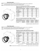
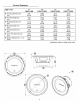

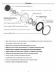
Table Of Contents

SPECIFICATIONS
PUNCH
Pl-SVG
8
11
1011
12
11
15
11
P1
5481
P1
S88
P1S410
1
P1
S81
0
P1S412
1
P1S812
P1S415
1
P1S815
Nominal Impedance (ohms)
4/8
4/8
4/8
4/8
Frequency Response
(Hz)
40-250
30-250
26-250
24-250
Voice
Coil
Diameter -
inch
1.50
(4-Layer)
1.50
(6-Layer)
1.50
(6-Layer)
1.50
(6-Layer)
(cm)
(3.81)
(3.81)
(3.81) (3.81)
Displacement -
cu.
ft.
0.024 0.043
0.048 0.060
(Liter)
(0.69)
(
1.22)
(
1.36)
(
1.70)
Fs
- Free Air Resonance
(Hz)
40
30
26
24
Qts 0.52/0.54
0.52/0.55
0.53/0.57
0.62/0.66
Vas
-
cu.
ft.
0.48
1.57
3.88
6.07
(Liter)
(13.5) (44.4)
(110.0) (
172.0)
Xmax -
inch
0.275
0.295 0.295
0.315
(cm)
(0.70)
(0.75)
(0.75) (0.80)
SPL
(dB
@ Iw/l
m)
84
85
86
87
Power Handling-Watts
(RMS)
150
150
150
200
(Peak)
300
300
300
400
Specifications subject
to
change
without
notice
..
+
20-
WIRING
CONFIGURATIONS
By
varying
the
wiring configuration
of
your
speakers you can
create
an
impedance load
to
match
your
system.Altering
the
wiring configurations
gives a range
of
options for impedance loads. Series, Parallel,
or
Series-Parallel wiring configurations
are
different techniques for wiring
speakers
that
provide different loads. Series configuration
is
a string
method
where
speakers
are
wired end
to
end. Parallel configuration
uses
two
or
more
speakers wired across
common
terminals.
Series-Parallel configuration combines both techniques.
Choose
the
wiring diagram
that
corresponds
to
the
number
of
woofers and
the
impedance
of
your
amplifier.
Parallel Wiring
(2)
4
ohm
SVC Speaker = 2 ohm
Load
SUB'NOOFER
CROSSOVERS
There
are
two
operational types
of
crossovers, passive and active.
Passive crossovers (coils
or
inductors)
are
placed on
the
speaker leads
between
the
amplifier and speaker.An active crossover
is
an electronic
filter
that
separates
the
audio signal fed
to
different amplifiers. For
optimum subwoofer performance,
we
recommend using an active
80-100Hz low-pass
crossover
at
12dB/octave.
5
Series/Parallel Wiring
®
40
(4) 4
ohm
SVC Speaker = 4 ohm
Load