2-CHANNEL AMPLIFIERS P200-2 P300-2 P400-2 P500-2 Installation & Operation Installation et fonctionnement Instalación y funcionamiento Einbau und Betrieb Installazione e funzionamento
INTRODUCTION Dear Customer, Congratulations on your purchase of the world's finest brand of car audio amplifiers. At Rockford Fosgate we are fanatics about musical reproduction at its best, and we are pleased you chose our product.Through years of engineering expertise, hand craftsmanship and critical testing procedures, we have created a wide range of products that reproduce music with all the clarity and richness you deserve.
GETTING STARTED Welcome to Rockford Fosgate! This manual is designed to provide information for the owner, salesperson and installer. For those of you who want quick information on how to install this product, please turn to the Installation Section of this manual. Other information can be located by using the Table of Contents.We, at Rockford Fosgate, have worked very hard to make sure all the information in this manual is current.
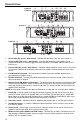
DESIGN FEATURES P200-2 P300-2 4 5 7 8 6 4 P400-2 5 7 5 7 6 9 10 8 9 10 13 14 9 10 8 6 P500-2 4 12 11 11 13 14 12 13 14 12 1. Power LED (Top of unit - Not Shown) – This Blue LED illuminates when the unit is turned on. 2. Thermal LED (Top of unit - Not Shown) – This Red LED illuminates if the amplifier internal components become too hot and engage the thermal protection.The amplifier will shut down to cool if this occurs. 3.
DESIGN FEATURES 12. RCA Input Jacks – The industry standard RCA jacks provide an easy connection for signal level input. They are nickel-plated to resist the signal degradation caused by corrosion. 13. REM Terminal – The heavy duty, nickel-plated captive c-clamp wire connector will accept wire sizes from 12 AWG to 24 AWG.This terminal is used to remotely turn-on and turn-off the amplifier when +12V DC is applied. 14.
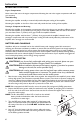
INSTALLATION MOUNTING LOCATIONS Engine Compartment Never mount this unit in the engine compartment. Mounting the unit in the engine compartment will void your warranty. Trunk Mounting Mounting the amplifier vertically or inverted will provide adequate cooling of the amplifier. Mounting the amplifier on the floor of the trunk will provide the best cooling of the amplifier.
INSTALLATION 5. Prepare the BLACK wire (Ground cable) for attachment to the amplifier by stripping 5/8" of insulation from the end of the wire. Insert the bare wire into the GROUND terminal and tighten the set screw to secure the cable in place. Prepare the chassis ground by scraping any paint from the metal surface and thoroughly clean the area of all dirt and grease. Strip the other end of the wire and attach a ring connector. Fasten the cable to the chassis using a non-anodized screw and a star washer.
INSTALLATION OR 2-Channel Wiring P200-2 P300-2 P400-2 P500-2 INPUT PASS-THRU INPUT OPERATION REMOTE PUNCH EQ (Option) NOTE:Previous (prior to 2007) Punch Bass and ParaPunch remotes will not work with these amplifiers. NOTE: Use the instructions that came with the remote for a variety of mountings that fit your preference. Quick Install 1. Using the screws supplied, install the mounting clip. 2. 3. +20 +18 +16 +14 Slip the remote onto the mounting clip until it snaps into place.
OPERATION ADJUSTING GAIN Crossover Switch To adjust the gain setting, turn the amplifier gains all the way down (counterclockwise).Turn the source unit volume up until distortion is audible and then turn it down a bit until the distortion is inaudible.This will be about all the way up on most source units. Next, increase the amplifier gain setting until adequate volume is achieved. NOTE:Best signal to noise and dynamic range are realized with the gain at minimum.
TROUBLESHOOTING 2. Bypass any and all electrical components between the stereo and the amplifier(s). Connect stereo directly to input of amplifier. If noise goes away the unit being bypassed is the cause of the noise. OR 3. Remove existing ground wires for all electrical components. Reground wires to different locations. Verify that grounding location is clean, shiny metal free of paint, rust etc. OR 4.
LIMITED WARRANTY INFORMATION Rockford Corporation offers a limited warranty on Rockford Fosgate products on the following terms: Length of Warranty Source Units, Speakers, Signal Processors and PUNCH Amplifiers – 1 Year POWER Amplifiers – 2 Years Any Factory Refurbished Product – 90 days (receipt required) What is Covered This warranty applies only to Rockford Fosgate products sold to consumers by Authorized Rockford Fosgate Dealers in the United States of America or its possessions.
INTRODUCTION Français Cher client, Toutes nos félicitations pour avoir acheté la meilleure marque d'amplificateurs pour automobile. Chez Rockford Fosgate nous sommes des mordus de la reproduction musicale à son meilleur. C’est pourquoi nous sommes heureux que vous ayez choisi notre produit. Des années d’expertise en ingénierie, de savoir-faire et d’essais poussés nous ont permis de créer une vaste gamme de produits capables de reproduire toute la clarté et la richesse musicales que vous méritez.
AVANT DE COMMENCER Bienvenue à Rockford Fosgate ! Ce manuel vise à informer le propriétaire, le vendeur et l’installateur de l’appareil. Si vous désirez apprendre rapidement comment installer ce produit, consultez la section Installation du manuel. Reportez-vous à la Table des matières pour d’autres informations. Nous nous efforçons de faire en sorte que toutes les informations contenues dans ce manuel soient à jour.
PARTICULARITÉS TECHNIQUES Français P200-2 P300-2 4 5 7 8 6 4 P400-2 5 7 5 7 6 9 10 8 9 10 13 14 9 10 8 6 P500-2 4 12 11 11 13 14 12 13 14 12 1. DEL d'alimentation (au-dessus de l'appareil - non montré) – Cette DEL bleue s'illumine lorsque l'appareil est allumé. 2. DEL thermique (au-dessus de l'appareil - non illustré) - Cette DEL rouge s'illumine si les composants internes de l'ampli surchauffent et déclenchent la protection thermique.
PARTICULARITÉS TECHNIQUES 12. Prises d'entrée RCA – Les prises RCA de norme industrielle permettent une connexion facile pour les entrées de signaux. Ils sont plaqués de nickelés pour résister à la détérioration de signal due à l'effet de la corrosion. 13. Borne REM - Le connecteur de fil robuste nickelé en C accepte des câbles de calibre 12 à 24 AWG. Cette borne permet d'allumer et d'éteindre à distance l'amplificateur lorsqu'un courant de +12 V c.c. est envoyé. 14.
INSTALLATION Français EMPLACEMENTS DE MONTAGE Compartiment moteur Ne montez jamais cet appareil dans le compartiment moteur. Cela entraînerait l’annulation de la garantie. Montage dans le coffre Un montage vertical ou inversé de l'ampli assure un refroidissement adéquat. Le montage de l'ampli sur le plancher du coffre assure un refroidissement optimal. Montage dans l’habitacle Le montage de l’ampli dans l’habitacle passager est acceptable à condition qu’il reçoive suffisamment d’air pour se refroidir.
INSTALLATION 5. Préparez le fil NOIR (câble de mise à la masse) qui devra être relié à l’ampli en dénudant 5/8 po (1,6 cm) de son extrémité. Insérez la partie dénudée dans la borne GND, puis fixez le fil en vissant la vis sans tête. Préparez la masse du châssis en grattant toute trace de peinture de la surface métallique et en nettoyant soigneusement pour éliminer tout dépôt de saleté et de graisse. Dénudez l’autre extrémité du fil et fixez un connecteur en anneau.
INSTALLATION Français OR Câblage à 2 voies P200-2 P300-2 P400-2 P500-2 INPUT PASS-THRU INPUT FONCTIONNEMENT TÉLÉCOMMANDE D'ÉGALISEUR PUNCH (en option) REMARQUE : Les modèles précédents (antérieurs à 2007) de télécommandes de basses Punch et Para-Punch ne fonctionneront pas avec ces amplificateurs. REMARQUE : Suivez le mode d'emploi livré avec la télécommande pour choisir parmi les différents types de montage celui que vous préférez. Installez Vite 1.
FONCTIONNEMENT RÉGLAGE DU GAIN Lorsque le sélecteur Crossover Switch Pour régler le gain, tournez le bouton de gain de l'ampli vers son niveau le plus bas (sens anti-horaire).Augmentez le volume de la source audio jusqu'à produire une distorsion audible, puis baissez-le jusqu'à ce que la distorsion devienne inaudible. Cela correspondant généralement au maximum du volume sur la plupart des unités source.Augmentez ensuite le gain de l'ampli jusqu'à ce que le volume soit adéquat.
DÉPANNAGE Français 2. Contournez tous les composants électriques situés entre la stéréo et l’ampli.Connectez la stéréo directement à l’entrée de l’ampli.Si le bruit disparaît,l’unité contournée est la cause du bruit. OU 3. Retirez les fils de masse de tous les composants électriques.Branchez de nouveau les fils à la masse,mais à des emplacements différents.Vérifiez que ceux-ci sont propres,que le métal est brillant sans trace de peinture,ni rouille,etc. OU 4.
INFORMATIONS SUR LA GARANTIE LIMITÉE Rockford Corporation offre une garantie limitée sur les produits Rockford Fosgate selon les termes suivants : Durée de la garantie Sources audio, haut-parleurs, processeurs de signaux et amplificateurs PUNCH — 1 an Amplificateurs POWER — 2 ans Tout produit remis à neuf en usine — 90 jours (reçu obligatoire) Couverture Cette garantie s'applique uniquement aux produits Rockford Fosgate vendus à des consommateurs par des distributeurs agréés Rockford Fosgate, aux États-
INTRODUCCIÓN Estimado cliente, Español Felicitaciones por su compra de la mejor marca del mundo de amplificadores para automóviles. En Rockford Fosgate somos fanáticos de la mejor reproducción musical y estamos agradecidos de que haya escogido nuestro producto. Con muchos años de experiencia en ingeniería, conocimiento del oficio y procedimientos de prueba críticos, hemos creado una amplia gama de productos para reproducción musical con toda la claridad y la riqueza que usted merece.
INICIO ¡Bienvenidos a Rockford Fosgate! Este manual ha sido creado para proporcionarle información al dueño, vendedor y técnico de instalación. Para quienes desean información rápida sobre cómo instalar este producto, por favor vean la Sección Instalación de este manual. El resto de la información puede encontrarse usando el Índice de Materias. Nosotros, en Rockford Fosgate hemos trabajado arduamente para asegurarnos que toda la información de este manual esté actualizada.
CARACTERÍSTICAS DEL DISEÑO P200-2 P300-2 4 5 7 8 Español 6 4 P400-2 5 7 5 7 6 9 10 8 9 10 13 14 9 10 8 6 P500-2 4 12 11 11 13 14 12 13 14 12 1. LED de alimentación (Parte superior de la unidad - no demostrado) – Este LED azul se ilumina cuando se enciende la unidad. 2. LED de temperatura (Parte superior de la unidad - No se muestra) - Este LED rojo se ilumina si los componentes internos del amplificador se calientan demasiado y accionan la protección térmica.
CARACTERÍSTICAS DEL DISEÑO 12. Enchufes RCA de entrada - Los enchufes RCA normativos en la industria brindan una conexión fácil para entrada de nivel de la señal. Están enchapados en niquelados, para resistir la degradación de la señal causada por la corrosión. 13. Terminales REM – Estos conectores niquelados de abrazadera "C" imperdibles para cable de servicio pesado aceptan cables de tamaño 12 a 24 AWG.
INSTALACIÓN LUGARES DE MONTAJE Compartimento del motor Nunca instale esta unidad en el compartimento del motor. Instalar la unidad en el compartimento del motor anulará su garantía. Instalación en el maletero Español El montaje vertical o invertido del amplificador proporcionará suficiente enfriamiento para el mismo. El montaje del amplificador en el piso del maletero proporcionará el mejor enfriamiento del mismo.
INSTALACIÓN 5. Prepare el cable NEGRO (cable a tierra) para conectarlo al amplificador, pelando 5/8 pulg. (1,6 cm) de la aislación del extremo final del cable. Inserte el cable sin aislación en el terminal GND (tierra) y ajuste el tornillo de fijación para asegurar el cable en su lugar. Prepare la conexión a tierra en el chasis raspando la pintura de la superficie de metal y limpie minuciosamente el polvo y la grasa del área. Pele el otro extremo del cable y conecte un anillo conector.
FUNCIONAMIENTO OR P200-2 P300-2 INPUT P400-2 P500-2 PASS-THRU Español Cableado de 2 canales INPUT FUNCIONAMIENTO REMOTE PUNCH EQ (Opcional) NOTA: Los controles remotos Punch Bass y Para-Punch previos (anteriores a 2007) no funcionarán con estos amplificadores. NOTA: Use las instrucciones que vinieron con el remoto para una variedad de montajes que se adapten a su preferencia. +20 Aprisa Instale 1. Instale el clip de montaje usando los tornillos proporcionados. 2.
FUNCIONAMIENTO Interruptor cruce Crossover de Switch AJUSTE DE GANANCIA Para ajustar la ganancia, gire las ganancias del amplificador totalmente hacia abajo (sentido contra horario). Suba el volumen de la unidad de origen hasta que pueda escuchar la distorsión y luego gire hacia abajo un poco hasta que no se pueda escuchar la distorsión. Esto será hasta arriba en la mayoría de las unidades fuentes. Luego, aumente el ajuste de ganancia del amplificador hasta que se obtenga un volumen adecuado.
SOLUCIÓN DE PROBLEMAS 2. Desvíe cualquiera y todos los componentes eléctricos entre el estéreo y los amplificadores.Conecte el estéreo directamente a la entrada del amplificador.Si el ruido desaparece el componente que está siendo desviado es la causa del ruido. O 3. Quite los cables a tierra existentes de todos los componentes eléctricos.Vuelva a conectarlos a tierra en lugares diferentes.Verifique que el sitio de conexión a tierra esté limpio,que sea metal brilloso sin pintura,óxido,etc.
INFORMACIÓN SOBRE LA GARANTÍA LIMITADA Rockford Corporation ofrece una garantía limitada para los productos Rockford Fosgate bajo los siguientes términos: Duración de la garantía Unidades Fuente, altavoces, procesadores de señales y amplificadores PUNCH—1 año Amplificadores POWER—2 años Cualquier producto de fábrica restaurado—90 días (comprobante de compra requerido) Qué está cubierto Esta garantía se aplica solamente a los productos Rockford Fosgate vendidos a consumidores por Concesionarios Autorizados
EINLEITUNG Liebe Kundin, lieber Kunde, wir gratulieren Ihnen zu Ihrem Kauf von Autoaudioverstärkern der besten Marke weltweit.Wir bei Rockford Fosgate sind Fanatiker, wenn es um die beste musikalische Reproduktion geht, und freuen uns darüber, dass Sie unser Produkt gewählt haben. Durch jahrelange Ingenieurserfahrung, Handwerkskunst und kritische Testverfahren haben wir ein weites Spektrum an Produkten geschaffen, die die Musik mit aller Klarheit und Klangschönheit reproduziert, die Sie verdienen.
HIER GEHT’S LOS Willkommen bei Rockford Fosgate! Diese Anleitung bietet dem Besitzer, Verkäufer und Einbauenden Informationen. Kurzgefasste Informationen zum Einbau dieses Produkts finden sich im Abschnitt „Einbau“ dieser Anleitung. Andere Informationen können Sie mithilfe des Inhaltsverzeichnisses auffinden. Wir bei Rockford Fosgate haben uns sehr darum bemüht, dass alle in dieser Anleitung enthaltenen Informationen auf dem neusten Stand sind.
DESIGNCHARAKTERISTIKEN P200-2 P300-2 4 5 7 8 6 4 Deutsch P400-2 5 7 5 7 6 9 10 8 9 10 13 14 9 10 8 6 P500-2 4 12 11 11 13 14 12 13 14 12 1. Betriebs-LED (Oberseite des Geräts - nicht gezeigt) – Diese blaue LED leuchtet auf, wenn das Gerät betriebsbereit ist. 2. Thermal-LED (Oberseite des Geräts - nicht gezeigt) - Diese rote LED leuchtet auf, wenn die internen Komponenten des Verstärkers zu heiß werden und der Thermalschutz aktiviert wird.
DESIGNCHARAKTERISTIKEN 12. RCA-Anschlüsse – Die genormten RCA-Anschlüsse ermöglichen einfaches Anschließen des Signalpegeleingangs. Sie sind platinplattiert, um der Signalverschlechterung verursachenden Korrosion zu widerstehen. 13. Fernbedienungsanschluss – Der hochbelastbare, vernickelte, unverlierbare C-Klemmkabelanschluss nimmt Kabel der Stärken 12 bis 24 AWG auf. Dieser Anschluss wird dazu benutzt, den Verstärker per Fernbedienung ein- bzw. auszuschalten, wenn +12 V Gleichstrom angelegt werden. 14.
EINBAU Metall angeschlossen sein, das an die Karosserie oder das Fahrgestell geschweißt ist. BEFESTIGUNGSSTELLEN Motorraum Das Gerät darf nicht im Motorraum installiert werden. Ein solcher Einbau führt zum Verlust der Garantie. Einbau im Kofferraum Aufrechter oder umgekehrter Einbau des Verstärkers bietet adäquate Kühlung des Verstärkers. Deutsch Befestigung des Verstärkers auf dem Boden des Kofferraums bietet die beste Kühlung des Verstärkers.
EINBAU 5. Das SCHWARZE Kabel (Erdungskabel) zur Befestigung am Verstärker durch Abziehen von 1,5 cm der Isolation am Kabelende vorbereiten. Das freigelegte Kabel in den GND-Pol einführen und die Befestigungsschraube anziehen. Den Untergrund am Fahrgestell durch Abkratzen der Farbe von der Metalloberfläche und sorgfältiges Reinigen des Bereichs von Schmutz und Schmiere vorbereiten. Die Isolation am anderen Ende des Kabels abziehen und einen ringförmigen Stecker anbringen.
EINBAU OR Zweikanalverkabelung P200-2 P300-2 INPUT P400-2 P500-2 PASS-THRU Deutsch INPUT BETRIEB PUNCH-EQ-FERNBEDIENUNG (wahlweise) HINWEIS: Vor 2007 hergestellte Modelle der Punch-Bass- und Para-Punch-Fernbedienungen können nicht mit diesen Verstärkern benutzt werden. HINWEIS: Die der Fernbedienung beiliegende Bedienungsanleitung beschreibt verschiedene Einbaumöglichkeiten.Wählen Sie diejenige, die Ihren Anforderungen entspricht. Bringen Sie Schnell An 1.
BETRIEB LAUTSTÄRKE (GAIN) EINSTELLEN Crossover-Schalter Crossover Switch Zur Einstellung der Lautstärke die Lautstärkeregler des Verstärkers ganz nach unten stellen (nach links drehen). Die Lautstärke des Source-Geräts erhöhen, bis eine Verzerrung hörbar ist, dann ein wenig verringern, bis die Verzerrung nicht mehr hörbar ist.An den meisten Source-Geräten bedeutet dies ganz nach oben.Als Nächstes die Lautstärkeeinstellung des Verstärkers erhöhen, bis eine adäquate Lautstärke erreicht ist.
FEHLERBESEITIGUNG 2. Alle elektrischen Komponenten zwischen der Stereoanlage und dem/den Verstärker(n) umgehen.Die Stereoanlage direkt am Verstärkereingang anschließen.Falls das Geräusch eliminiert ist,ist das umgangene Gerät die Ursache des Geräuschs. ODER 3. Die vorhandenen Erdungskabel aller elektrischen Komponenten entfernen.Die Kabel an anderen Stellen wieder erden.Prüfen, ob die Erdungsstelle sauberes,glänzendes Metall ist,das frei von Farbe,Rost usw.ist. ORER 4.
INFORMATIONEN ZUR BESCHRÄNKTEN GARANTIE Rockford Corporation bietet für Rockford Fosgate Produkte eine beschränkte Garantie zu folgenden Bedingungen: Laufzeit der Garantie Source-Geräte, Lautsprecher, Signalprozessoren und PUNCH-Verstärker – 1 Jahr POWER-Verstärker – 2 Jahre Alle werkseitig aufgearbeiteten Produkte – 90 Tage (Quittung erforderlich) Was gedeckt ist Diese Garantie erstreckt sich nur auf Rockford Fosgate Produkte, die von Rockford Fosgates Vertragshändlern an Verbraucher in den Vereinigten S
INTRODUZIONE Egregio cliente, Congratulazioni per aver acquistato la miglior marca di amplificatori per auto a livello mondiale.Alla Rockford Fosgate, siamo fanatici per quanto riguarda la miglior riproduzione musicale e siamo compiaciuti che abbiate scelto il nostro prodotto. Dopo anni di competenza ingegneristica, maestria manuale e procedure di prova critica, abbiamo creato una larga gamma di prodotti che riproducono la musica con la limpidezza e la pienezza che vi meritate.
PRIMI PASSI Benvenuti alla Rockford Fosgate! Questo manuale è stato concepito per fornire ragguagli al proprietario, al rivenditore e all’installatore. Per coloro che desiderano informazioni rapide circa l’installazione di questo prodotto, vi preghiamo di consultare la sezione Installazione di questo manuale. Altri ragguagli sono disponibili attraverso l’Indice. Alla Rockford Fosgate, abbiamo fatto di tutto per assicurarci che tutte le informazioni contenute in questo manuale fossero d’uso corrente.
CARATTERISTICHE DEL DESIGN P200-2 P300-2 4 5 7 8 6 4 P400-2 5 7 Italiano 5 7 6 9 10 8 9 10 13 14 9 10 8 6 P500-2 4 12 11 11 13 14 12 13 14 12 1. LED alimentazione (parte superiore dell'unità - non indicato) – Questo LED blu si accende quando l'unità viene accesa. 2.
CARATTERISTICHE DEL DESIGN 11. Spinotti passa-attraverso RCA – Il passa-attraverso fornisce una fonte conveniente per concatenare a margherita un amplificatore supplementare senza far scorrere un altro paio di cavi RCA dalla parte anteriore del veicolo all’ubicazione posteriore dell’amplificatore. 12. Spinotti d’ingresso RCA – Gli spinotti RCA standard di fabbrica forniscono un collegamento facile per l’ingresso del livello di segnale.
INSTALLAZIONE POSIZIONAMENTO Scompartimento del motore Non montate mai questa unità nello scompartimento del motore. Ciò annullerà la vostra garanzia. Montaggio nel bagagliaio Il montaggio dell'amplificatore in posizione verticale o invertita sarà sufficiente a fornire adeguato raffreddamento all'unità. Se l'amplificatore viene montato sul fondo del bagagliaio, si ottiene il migliore raffreddamento dell'unità.
INSTALLAZIONE 5. Preparate il filo NERO (cavo della messa a terra) per poterlo attaccare all’amplificatore, spelando via 13 mm di isolante dall’estremità del filo. Inserite il filo spelato dentro il terminale GND e stringete la vite di arresto per fissare il cavo. Preparate la messa a terra del telaio raschiando via la vernice dalla superficie metallica e pulitela accuratamente, rimovendo ogni traccia di lubrificazione e di sudiciume.
INSTALLAZIONE OR Cablaggio a 2 canali P200-2 P300-2 INPUT P400-2 P500-2 PASS-THRU INPUT FUNZIONAMENTO Italiano EQUALIZZATORE PUNCH A DISTANZA (opzionale) NOTA: i vecchi comandi a distanza Punch Bass e Para-Bass (quelli prima del 2007) non funzioneranno con questi amplificatori. NOTA: Utilizzare le istruzioni fornite con il comando a distanza per determinare lo schema di installazione preferito tra quelli possibili. +20 Rapidamente Installi 1.
FUNZIONAMENTO Interruttore di crossover Crossover Switch REGOLAZIONE DEL GUADAGNO Per regolare l'impostazione per il guadagno, abbassare completamente i guadagni per l'amplificatore (ruotando in senso antiorario).Alzare il volume dell’unità di fonte finché la distorsione non diventi udibile, e poi abbassarlo finché la distorsione non sia più udibile. Nella maggior parte delle unità, ciò avviene quasi al volume massimo.
INDIVIDUAZIONE/RIPARAZIONE GUASTI Procedura 5:Controllate l’amplificatore se si verificasse un rumore eccessivo a livello del motore. 1. Fate scorrere tutti i fili che portano segnali (RCA,cavi degli altoparlanti) lontano dalla tensione e dai fili della messa a terra. OPPURE 2. Bipassate tutte le componenti elettriche tra il sistema stereofonico e l’amplificatore(i).Collegate il sistema stereofonico direttamente all’entrata dell’amplificatore.
INFORMAZIONI INERENTI ALLA GARANZIA LIMITATA La Rockford Corporation offre una garanzia limitata sui prodotti della Rockford Fosgate alle seguenti condizioni: Lunghezza della garanzia Unità di fonte, altoparlanti, elaboratori di segnali e amplificatori PUNCH — 1 anno Amplificatori POWER — 2 anni Prodotti rimessi a nuovo dalla fabbrica — 90 giorni (è necessaria la ricevuta) Ciò che è coperto dalla garanzia Questa garanzia è solamente applicabile ai prodotti della Rockford Fosgate venduti a clienti da parte
Installation assistance availible at: www.rockfordfosgate.com/rftech Rockford Fosgate Rockford Corporation 546 South Rockford Drive Tempe, Arizona 85281 U.S.A. In U.S.A., (480) 967-3565 - Customer Service 1-800-669-9899 In Europe, Fax (49) 8503-934014 In Japan, Fax (81) 559-79-1265 www.rockfordfosgate.com 03/08 B.M.