PUNCH 4020 DSM 4-C HANNEL A MPLIFIER I NSTALLATION & O PERATION ® ®
Dear Customer, Congratulations on your purchase of the world's finest brand of car audio amplifiers. At Rockford Fosgate we are committed to musical reproduction at its best, and we are pleased you chose our product. Through years of engineering expertise, hand craftsmanship and critical testing procedures, we have created a wide range of products that reproduce music with all the clarity and richness you deserve.
TABLE OF CONTENTS Introduction ...................................................................................... 1 Punch 4020 Amplifier Accessory Pack .............................................. 1 Rockford Fosgate Accessories ............................................................ 2 Technical Design Features ................................................................ 3 Punch 4020 Design Features .............................................................
INTRODUCTION The Punch 4020 is a 4-channel amplifier which offers 20 Watts per channel when driven into 4 Ohms. The amplifier utilizes a 2/ 4 input selector switch and XCard crossovers. When building a 4-channel amplifier, a major design challenge is to maintain sound quality in a limited space. For the Punch 4020, Rockford Fosgate Engineers designed the Trans•Ana topology which is a fast, short loop circuit allowing the output stage to be driven with a low voltage drive signal.
R O C K F O R D F O S G AT E A C C E S S O R I E S The following accessories were designed to enhance the performance of the Punch 4020 amplifier. Energy Storage Capacitor (PCH-C1) The Punch 1 farad capacitor is used to provide extra current needed by amplifiers to reproduce musical transients. The Punch Cap also has the natural ability to filter DC ripple caused by the alternator which can result in noise in the system.
T ECHNICAL D ESIGN F EATURES ◆ trans•ana The trans•ana (TRANS conductance Advanced Non-multiplying Amplifier) is a novel circuit that utilizes a short-loop complementary topology and advanced Real Time Protection circuitry. THE RESULT: An amplifier design with the benefits of tube and bipolar transistor amplifier design without the limitations of either.
to be obtained in amplifiers of desirable package size without resorting to “amplifier-on-a-chip” shortcuts. These advantages are shown below in Figure 1. THE RESULT: Less connections, improved reliability, shorter signal paths, superior signal-to-noise ratio and awesome sonic performance.
◆ XCard (Internal Crossover) The Punch 4020 amplifier utilizes internal active crossovers. These crossovers have many performance advantages such as using discrete components for exact frequency adjustments which are far superior to potentiometers. Additionally, the XCard can be configured for high-pass, low-pass and full range operation. With slight modification, many crossover frequencies and slope configurations can be achieved.
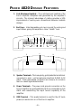
P UNCH 4020 D E S I G N F E AT U R E S 1. Cast Aluminum Heatsink – The cast aluminum heatsink of the Punch amplifier dissipates heat generated by the amplifier's circuitry. The inherent advantage of casting provides a 30% improvement of cooling over conventional extrusion heatsink designs. 2. End Caps – Interchangeable end caps conceal the wiring and input cables, giving the amplifier a clean “stealth” look.
6. RCA Input Jacks – The industry standard RCA jack provides an easy connection for signal level input. They are gold-plated to resist the signal degradation caused by corrosion. 7. Signal Input Switch – This switch allows selection of 2 channel or 4 channel source unit feed. 8. Input Sensitivity Controls – The input level controls are preset for 500mV which will match the output of most source units. They can be adjusted to match input levels ranging from 150mV to 3V. 9.
I N S TA L L AT I O N C O N S I D E R AT I O N S The following is a list of tools you will need for installing the Punch amplifier: Allen wrenches 7/64" & 3/32" (included) Wire strippers Electric hand drill w/assorted bits Wire crimpers Voltmeter Battery post wrench Wire cutters Assorted connectors This section focuses on some of the vehicle considerations for installing your new Punch amplifier.
M OUNTING L OCATION The mounting location and position of your amplifier will have a great effect on its ability to dissipate the heat generated under normal operation. The design of our cast aluminum heatsink serves to easily dissipate the heat generated over a wide range of operating conditions. However, to maximize the performance of your amplifier, care should be taken to ensure adequate ventilation.
B ATTERY AND C HARGING Amplifiers will put an increased load on the vehicle's battery and charging system. We recommend checking your alternator and battery condition to ensure that the electrical system has enough capacity to handle the increased load of your stereo system. Stock electrical systems which are in good condition should be able to handle the extra load of any Rockford amplifier without problems, although battery and alternator life can be reduced slightly.
3. Prepare a length of cable to be used for the ground connection. Strip 5/8" of insulation from the end of the cable as described above and connect to the appropriate terminal of the amplifier. Prepare the chassis ground by scraping any paint from the metal surface and thoroughly clean the area of all dirt and grease. Strip the other end of the wire and attach a ring connector. Fasten the cable to the chassis using a screw. 4.
USING THE XCARD The crossover functions are controlled through the use of an XCard and can be set for high-pass, low-pass or full range operation. These cards are shipped in the most common frequency. Each crossover card has two faces: one face operates Full Range, the other has arrows to indicate the edge for selecting HP (high-pass) or LP (low-pass) operation. Orient the card with the desired operating edge, indicated by the arrow, toward the socket terminals inside the amplifier.
4020 P OW E R C ON N E CTIONS 4 5 10 POWER REM B+ Connect to remote turn-on lead of source unit. GND Connect to chassis ground of vehicle* Less than 18" Connect to B+ of battery with a 30 amp fuse. *Keep grounds as short as possible.
SAMPLE WIRING DIAGRAMS 4-CHANNEL STEREO L – + R (Bridged Mono) Front Speakers + – + – Front Gain + R R L L Front Rear Rear Gain Rear Front – L + – R + (Bridged Mono) Rear Speakers – 2Ω Minimum High Frequency – – + 2Ω Minimum Low Frequency Rear XCard* Front XCard* LP HP XCard 1 XCard 2 *Note: XCard can be inserted in HP, LP, or Full Range. • • • • • Signal input switch to 4 channel input. Gain for Front and Rear operate independently. Front is operating in stereo.
4-CHANNEL – STEREO FRONT MONO REAR Rear Front – + R (Bridged Mono) Front Speakers – Front Gain L L L Front Rear Rear Gain R R + – L – + – + – R + + – 4Ω Minimum Low Frequency 2Ω Minimum High Frequency Rear XCard* + (Bridged Mono) Rear Speakers Front XCard* LP HP XCard 1 XCard 2 *Note: XCard can be inserted in HP, LP, or Full Range. • • • • • • Signal input switch to 4 channel input. Gain for Front and Rear operate independently. Front is operating in stereo.
2-CHANNEL – MONO Rear Front – + R – (Bridged Mono) Front Speakers + Front Gain L L L Rear Front – – L + – R + 4Ω Minimum Low Frequency Front XCard* LP LP XCard 1 XCard 2 *Note: XCard can be inserted in HP, LP, or Full Range. • • • • + (Bridged Mono) Rear Speakers – 4Ω Minimum Low Frequency Rear XCard* Rear Gain R R + Signal input switch to 2 channel input. Gain for Front and Rear operate independently. Front is operating in mono. Rear is operating in mono.
4-CHANNEL – STEREO/MONO FRONT STEREO REAR Rear L – + R – (Bridged Mono) Front Speakers + – R L L Front + 2Ω Minimum High Frequency R – Rear Gain + Front Gain Front Rear L + – R + (Bridged Mono) Rear Speakers – 2Ω Minimum High Frequency – + – + + – 2Ω Minimum High Frequency 4Ω Minimum Low Frequency Rear XCard* Front XCard* HP XCard 1 Full Range XCard 2 Note: XCard can be inserted in HP, LP, or Full Range. • • • • • Signal input switch to 4 channel input.
TROUBLESHOOTING Symptom Amplifier does not turn on. (Power LED is off) Amplifier has no sound. (Power LED is on) Diagnosis Remedy Voltage applied to the REM terminal of the amplifier is not between 10.5 and 15.5 volts or there is no voltage present. Check the alternator, battery, fuse, and wiring and repair as necessary. If the voltage is above 15.5 volts, have the electrical system inspected by an authorized car service center. Voltage to the B+ terminal of the amplifier is not between 10.5 and 15.
Symptom Speaker Output Low or Distorted Amplifier Noise (Turn-on Pop) Diagnosis Remedy Input gain signal for amplifier set too low. Readjust input gains of amplifier. Source unit output too low. Check system with known working source and repair or replace orignal source as needed. Speakers wired out of polarity from the left to right channel. Check speaker polarity and correct as needed. XCards are missing or not placed properly in crossover slots and/or switch not properly selected.
Symptom Engine Noise on the Speaker Outputs of the Amplifier Diagnosis Remedy Speaker leads are shorted to each other or to the chassis of the vehicle. Disconnect existing speakers and test with known working speakers. If engine noise is gone, check and repair wiring and installation of speakers as necessary. RCA input from source unit is not connected or not functioning properly. Check connections, substitute with known working cables and repair or replace as necessary.
DYNAMIC POWER MEASUREMENTS About the Dynamic Power Measurements The Audio Graph PowerCube is a test instrument used to measure the output of an amplifier in accordance with IHF-202 industry standards. The IHF-202 standard is a dynamic power measurement and was developed as a means of measuring power in a manner that best represents the Real World operation of an amplifier. Many manufacturers, including Rockford Fosgate, at times will measure amplifier power into a fixed resistor (4 Ohm, 2 Ohm).
Information Cubed The data acquired in the testing procedure is then graphed in the form of a 3-dimensional cube. Hence the name PowerCube. The Phase Angle is expressed on the horizontal axis, the Output Voltage is presented on the vertical axis and the Impedance is displayed on the Z axis. Output Power, in watts, is listed on the left hand side for each impedance at each phase angle. AudioGraph – The PowerCube x2 = STEREO MONO = BRIDGED MONO I M P E D A N C E Amplifier: PUNCH AMP 14.
S P E C I F I C AT I O N S Continuous Power Rating (Competition Standard) - Measured at 13.8V RMS continuous power per channel, all channels 20 Watts driven into a 4Ω load from 20-20,000Hz with less than 0.05% Total Harmonic Distortion (THD) RMS continuous power per channel, all channels driven into a 2Ω load from 20 to 20,000Hz, with less than 0.1% THD 30 Watts RMS continuous power bridged into a 4Ω load from 20 to 20,000Hz, with less than 0.
W A R R A N T Y I N F O R M AT I O N Rockford Fosgate warrants all electronics to the original consumer/purchaser to be free from defects in materials or workmanship for a period of three (3) years. We will cover parts and labor provided the product was purchased from an Authorized Rockford Fosgate Dealer. This warranty does not apply to any product on which the seals and/or serial number have been broken, removed, tampered with, defaced or altered in any manner.
Rockford Fosgate Rockford Corporation 546 South Rockford Drive Tempe, Arizona 85281 U.S.A. In U.S.A.