punch ® ® car audio for fanatics 2-Channel Amplifiers Operation & Installation ®
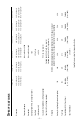
–i– Input Impedance Adjustable (0, +6, +12dB) ATC Fuse Type Equalization (45Hz Punch Bass) 15A Battery Fusing Rating (External to Amplifier) Protection Input Sensitivity (+0dB gain overlap) Source Unit Compatibility (+15dB gain overlap) IM Distortion (IHF) Slew Rate Damping Factor @ 4Ω (at output connector ) 2.60" (6.60cm) H 9.60" (24.38cm) W 8.70" (22.04cm) PUNCH 360 2.60" (6.60cm) H 9.60" (24.38cm) W 9.70" (24.
– ii – 50 Watts x 2 Per channel into a 4Ω Load 60 Watts x 2 80 Watts x 2 80Hz 100 Watts x 1 RMS continuous power mono into a 4Ω load from 20 to 20,000 Hz, with less than 0.1% Total Harmonic Distortion (THD) Signal-to-Noise Ratio Crossover Slope Crossover Frequency 50 Watts x 2 25 Watts x 2 RMS continuous power per channel, both channels driven into a 2Ω load from 20 to 20,000 Hz, with less than 0.
Dear Customer, Congratulations on your purchase of the world's finest brand of car audio amplifiers. At Rockford Fosgate we are fanatics about musical reproduction at its best, and we are pleased you chose our product. Through years of engineering expertise, hand craftsmanship and critical testing procedures, we have created a wide range of products that reproduce music with all the clarity and richness you deserve.
TABLE CONTENTS OF Specifications .............................................................................................. i Introduction ................................................................................................ 1 Punch Amplifier Accessory Pack ................................................................... 1 2-Channel Feature Chart .............................................................................. 2 Design Features .............................................
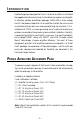
INTRODUCTION Rockford engineers designed the Punch 2-channel amplifiers to withstand the rugged automotive environment while delivering superior sound quality in a flexible, reliable, and efficient package. TRANS•ANA is a low voltage circuit in the preamp stage of all Punch amplifiers that lets the music sound crystal clear and very real, even when played at high volume levels.
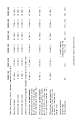
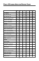
PUNCH 2-CHANNEL AMPLIFIER FEATURE CHART 100 150 250 360 500 800 2 2 2 2 2 2 RMS Power Mono (4Ω) 25x2 37.5x2 62.
Adjustable Punch Bass (0dB/+6dB/+12dB @ 45Hz) Variable Punch Bass 100 x 150 – 250 – 360 – 500 – 800 – – x x x x x (0dB ~+18dB @ 45Hz) Adjustable Xover (80Hz) Variable Xover (50Hz ~ 210Hz) Crossover Slope (Butterworth) HP/FULL/LP5 HP/FULL/LP5 – – 5 – 5 – 5 HP/FULL/LP HP/FULL/LP HP/FULL/LP HP/FULL/LP5 12dB 12dB 12dB 12dB – 12dB – 12dB - - - - - - B+ Fuse Size 15A ATC 20A ATC 30A ATC 40A ATC 50A ATC 60A ATC Dimensions (H x W x L) 2.60" x 2.60" x 2.60" x 2.60" x 2.
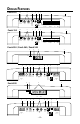
D ESIGN FEATURES Punch 100 9 8 4 7 5 1 2 3 R+ L+ LED L– HP–Full–LP 80Hz Crossover Punch 150 6 Left Input 9 8 R– 0dB +6dB REM Gain +12dB High Punch R+ L+ Level Bass R– L– Input Right Input 4 7 6 5 + Left – + Right – 3 B+ GND 2 1 R+ L+ LED R– L– HP–Full–LP 80Hz Crossover Left Input Right Input REM Gain Punch Bass High R+ L+ Level Input R– L– + Left – + Right – B+ GND Punch 250 / Punch 360 / Punch 500 9 2 3 1 LED REM 2 7 8 190 210 Hz GND 6 4 6 50 55 1
1. Cast Aluminum Heatsink – The cast aluminum heatsink of the Punch amplifier dissipates heat generated by the amplifier's circuitry. The inherent advantage of casting provides a 30% improvement of cooling over conventional extrusion heatsink designs. 2. Speaker/Power Terminals – These gold-plated connectors are used for the connection of speaker and power wire and are immune to corrosion that can cause signal degradation.
I NSTALLATION C ONSIDERATIONS The following is a list of tools you will need for installing the Punch amplifier: Allen wrenches 9/64" & 3/32" (included) Voltmeter Wire strippers Battery post wrench Electric hand drill w/assorted bits Wire cutters 17' (518.16cm) Red Power Wire Assorted connectors 12' (365.76cm) Remote Turn-On Wire Wire crimpers 1.5' (45.72cm) Black Grounding Wire This section focuses on some of the vehicle considerations for installing your new Punch amplifier.
M OUNTING L OCATION The mounting location and position of your amplifier will have a great effect on its ability to dissipate the heat generated during normal operation. The design of our cast aluminum heatsink serves to easily dissipate the heat generated over a wide range of operating conditions. However, to maximize the performance of your amplifier, care should be taken to ensure adequate ventilation.
B ATTERY AND C HARGING Amplifiers will put an increased load on the vehicle's battery and charging system. We recommend checking your alternator and battery condition to ensure that the electrical system has enough capacity to handle the increased load of your stereo system. Stock electrical systems which are in good condition should be able to handle the extra load of any Rockford amplifier without problems, although battery and alternator life can be reduced slightly.
3. Strip 1/2" from the battery end of the power cable and crimp a large ring terminal to the cable. Use the ring terminal to connect to the battery positive terminal. Do not install the fuse at this time. 4. Prepare the Ground cable for attachment to the amplifier by stripping 1/ 2" of insulation from the end of the wire. Insert the bared wire into the GND terminal and tighten the set screw to secure the cable in place.
USING PASSIVE CROSSOVERS A passive crossover is a circuit that uses capacitors and/or coils and is placed on speaker leads between the amplifier and speaker. The crossover delegates a specific range of frequencies to the speaker for optimum driver performance. A crossover network can perform one of three functions: High-Pass (capacitors), Low-Pass (inductors or coils) and Bandpass (combination of capacitor and coil). The most commonly used passive crossover networks are 6dB/octave systems.
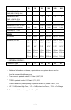
a d v a n c e d TABLE OF CROSSOVER COMPONENT VALUES C L 6dB/Octave Low-Pass 6dB/Octave High-Pass Speaker Impedance Freq. Hertz 2 OHMS 8 OHMS 4 OHMS C L C L L C 80 100 130 4.1mH 3.1mH 2.4mH 1000µF 800µF 600µF 8.2mH 6.2mH 4.7mH 500µF 400µF 300µF 16mH 12mH 10mH 250µF 200µF 150µF 200 260 400 1.6mH 1.2mH .8mH 400µF 300µF 200µF 3.3mH 2.4mH 1.6mH 200µF 150µF 100µF 6.8mH 4.7mH 3.3mH 100µF 75µF 50µF 600 800 1000 .5mH .41mH .31mH 136µF 100µF 78µF 1.0mH .82mH .62mH 68µF 50µF 39µF 2.
® I NSTALLATION Power Connections Punch 100 / Punch 150 R+ L+ LED L– HP–Full–LP 80Hz Crossover Left Input Right Input R– 0dB +6dB REM Gain +12dB High Punch R+ L+ Level Bass R– L– Input + Left – + Right – Connect to remote turn-on lead of source unit P100 15A P150 20A B+ GND Connect to chassis ground of vehicle* Less than 18" Connect to B+ of battery with appropriate fuse value *Keep grounds as short as possible Power Connections Punch 250 / Punch 360 / Punch 500 LED REM P250 - 3 0A P36
® Power Connections Punch 800 LED REM B+ GND Connect to remote turn-on lead of source unit – + P800 60A 1 Connect to chassis ground of vehicle* Less than 18" Optional Energy Storage Capacitor Connect to B+ of battery with appropriate fuse *Keep grounds as short as possible 1 Fuse not supplied with amplifier RCA Inputs High Level Inputs R AUD VOL DISC AMFM PWR ST ® Ch LD RDM RPT CLOCK AUTO DSPL P.SCN SEL ILLUM LOUD D.
® Crossover Operation 210 190 Hz 50 145 R+ L+ 55 110 R– L– Punch Crossover Left Bass Frequency Gain Left Input Right Input Right Gain High R+ L+ Level Input R– L– Speaker + L HP–Full–LP Crossover 65 80 – 210 Hz Low-Pass (LP) Operation 145 2 1 50 190 110 2 1 50 55 110 65 80 – High-Pass (HP) Operation Hz 210 145 55 65 80 HP – Full – LP Crossover Frequency +3 +2 +1 0 –1 –2 –3 –4 –5 –6 –7 –8 –9 –10 –11 –12 R 2 1 190 Speaker + HP – Full – LP Crossover Frequency
® Stereo Operation Punch 100 / Punch 150 RCA Input LED Left Input 0dB +6dB REM Gain +12dB High Level Punch Input Bass Right Input + – Left Output + Right Output – B+ GND + HP–Full–LP 80Hz Crossover – 2Ω min. 2Ω min.
® Mono Operation Punch 100 / Punch 150 RCA Input LED HP–Full–LP 80Hz Crossover Left Input 0dB +6dB REM Gain +12dB High Level Punch Input Bass Right Input + – + Left Output Right Output + – B+ GND – 4Ω min.
® Stereo/Mono Operation Punch 100 / Punch 150 RCA Input LED HP–Full–LP 80Hz Crossover Left Input 0dB +6dB REM Gain +12dB High Level Punch Input Bass Right Input + – + Left Output Right Output – B+ GND + – 2Ω min. 2Ω min. – + + – 4Ω min.
SYSTEM DIAGRAMS 2-Way System R AUD VOL PWR DISC AMFM ® ST Ch LD RDM RPT CLOCK AUTO ILLUM DSPL P.SCN LOUD SEL D.
3-Way System Using single voice coil woofers R AUD VOL PWR CLOCK DISC AMFM ST ® Ch LD RDM RPT AUTO DSPL SEL ILLUM P.SCN LOUD D.
3-Way System Using dual voice coil woofers R AUD VOL PWR CLOCK DISC AMFM Ch LD RDM RPT ST ® Sub AUTO DSPL LOUD SCAN RPT RDM DIM PAUSE 1 2 3 4 5 6 TUNE ® Rear Front Crossover SEL ILLUM P.SCN D.
TROUBLE-S H O O T I N G TROUBLESHOOTING Symptom Amplifier does not turn on (Power LED is off) Amplifier has no sound (Power LED is on) Speaker Output Low or Distorted Diagnosis Remedy Voltage applied to the REM terminal of the amplifier is not between 10.5 and 15.5 volts or there is no voltage present. Check the alternator, battery, fuse, and wiring and repair as necessary. If the voltage is above 15.5 volts, have the electrical system inspected by an authorized car service center.
TROUBLE-S H O O T I N G Symptom Amplifier Noise (Turn-on Pop) Diagnosis Remedy Voltage spike from remote turn-on lead is entering through REM input terminal. Use a different 12 volt source for REM lead of amplifier (i.e., battery direct). If noise is eliminated, use a relay to isolate amplifier from noisy turn-on output. Noise is radiating into RCA signal cable. Check connections, run the RCA cables on a different route away from sources of high current. Bad component in the signal chain.
D YNAMIC P OWER M EASUREMENTS About the Dynamic Power Measurements The Audio Graph PowerCube is a test instrument used to measure the output of an amplifier in accordance with IHF-202 industry standards. The IHF-202 standard is a dynamic power measurement and was developed as a means of measuring power in a manner that best represents the Real World operation of an amplifier. Many manufacturers, including Rockford Fosgate, at times will measure amplifier power into a fixed resistor (4 ohm, 2 ohm).
Information Cubed The data acquired in the testing procedure is then graphed in the form of a 3-dimensional cube, hence the name PowerCube. The Phase Angle is expressed on the horizontal axis, the Output Voltage is presented on the vertical axis and the Impedance is displayed on the Z axis. Output Power, in watts, is listed on the left hand side for each impedance at each phase angle. Audio Graph – The PowerCube™ x2 = STEREO MONO = BRIDGED MONO I M P E D A N C E Amplifier: PUNCH 200.2 14.
L IMITED W A R R A N T Y I N F O R M AT I O N Rockford Corporation offers a limited warranty on Rockford Fosgate products on the following terms: • Length of Warranty 3 years on electronics 2 years on source units 1 year on speakers 90 days on electronic B-stock (receipt required) 90 days on speaker B-stock (receipt required) • What is Covered This warranty applies only to Rockford Fosgate products sold to consumers by Authorized Rockford Fosgate Dealers in the United States of America or its possessions.
A A TI N TI M R R O N TE O N FO IN A L IN – 26 –
LEA DETENIDAMENTE LAS SIGUIENTES INSTRUCCIONES DE INSTALACION DEL PRODUCTO. EVITARA POSIBLES DAÑOS A VD., AL VEHICULO O AL PRODUCTO. INTRODUCCION Los ingenieros de Rockford han diseñado los amplificadores Punch para ofrecer en el dificil entorno de un automóvil una calidad de sonido superior en un producto flexible, fiable y eficiente.
Terminal REM Conecte el cable REM a un punto de +12V con mutable. La señal se suele coger de la salida auto antena del radio cassette si este no tiene salida remote. Funcionamiento Estereo/Mono RCA Input 190 210 Hz 50 145 Punch Bass R+ L+ 55 110 Crossover Left Frequency Gain Left Input L HP–Full–LP Crossover High Level Input R+ L+ Right Gain Right Input Speaker + R– L– 65 80 – Speaker R– L– + R – + – 2Ω min. 2Ω min. – + + – 4Ω min.
ATTENTION: Veuillez lire les instructions suivantes pour l'installation de cet amplifcateur. Ne pas les suivre pourrait causer des blessures ou endommager le véhicule. INTRODUCTION Les ingénieurs de Rockford Fosgate ont conçu l'amplificateur Punch pour supporter l'environnement rude de l'automobile en délivrant une qualité de son supérieure dans un ensemble efficace, fiable et flexible.
Terminal GND Préparez une longueur de câble pour la connexion à la masse. Préparez le châssis en grattant la peinture de la surface métallique et nettoyez la saleté et l'huile. Attachez le câble au châssis avec une vis. Terminal REM Connectez le fil REM à une commande 12 volts positive de la source. La commande 12 volts est habituellement prise sur la sortie antenne électrique de la source ou la commande accessoire.
BITTE LESEN SIE DIESE GEBRAUCHSANLEITUNG ZUERST SORGFÄLTIG DURCH. DAS KANN SIE VOR DEM FALSCHEN EINSATZ, AUSFALLEN ODER SOGAR BESCHÄDIGUNG DES PRODUKTES ODER IHRES FAHRZEUGES SCHÜTZEN. EINLEITUNG Rockford Ingenieure haben die Punch Verstärker entwickelt.
β GND Anschluβ Preparieren Sie Ihr Kabel für die Negativ Leitung (Erdung). Preparieren Sie die Anschlubstelle des Erdungskabels, indem Sie das Metall gründlich reinigen und vom Lack befreien. Befestigen Sie nun die Erdung an dieser Stelle mit einer Schraube. β REM Anschluβ Verbinden Sie das Ein-und Ausschaltungskontroll-Kabel mit Ihrem Radio (12 Volt positiv). Normalerweise verwenden Sie hierfür die Ant.-Remote Ihres Radios oder ein eigens dafür vorgesehenes Kabel (Amp-Remote).
ATTENZIONE: SI PREGA DI LEGGERE LE SEGUENTI ISTRUZIONI PER L'INSTALLAZIONE DI QUESTO PRODOTTO. IL NON SEGUIRLE POTREBBE RISULTARE SERIAMENTE DANNOSO PER LA PERSONA O PER IL VEICOLO. INTRODUZIONE Gli ingenieri Rockford hanno progettato la serie di amplificatori Punch per resistere all'ostico ambiente automobilistico mentre suonano con una musicalitá superiore, offrendo un insieme versatile, affidabile ed efficiente.
Terminale GND (cavo negativo) Decidere la lunghezza del cavo e terminarlo. Preparare la massa grattando la vernice dal telaio dell'auto ed eliminando tracce di olio o sporco. Fissare il cavo di massa al telaio con una vite. Terminale REM (Consenso di accensione) Collegare il cavo REM ad un positivo presente solo ad autoradio accesa (normalmente il cavo pilota dell'antenna elettrica o il cavo accessori dell'autoradio).
ance by m r o f r pe ximum a m t e G timate l u e h g for t surfin gns at: i s e d system Punch ate.com g s o f d ckfor www.ro HANDCRAFTED IN THE UNITED STATES OF AMERICA This product is designed, developed and assembled in the USA by a dedicated group of American workers. The majority of the components used in the construction of this product are produced by American companies.