PUNCH AUDIOPHILE SYSTEM RFA-414 RFA-514 RFA-614 INSTALLATION & OPERATION ® ®
Dear Customer, Congratulations on your purchase of the world's finest brand of car audio speakers. At Rockford Fosgate we are fanatics about musical reproduction at its best, and we are pleased you chose our product. Through years of engineering expertise, hand craftsmanship and critical testing procedures, we have created a wide range of products that reproduce music with all the clarity and richness you deserve.
TABLE OF CONTENTS Introduction ............................................................................................... Amplifier Accessory Pack ......................................................................... 1 Technical Design Features ....................................................................... 2 Design Features ........................................................................................ 5 Installation Considerations ..............................................
INTRODUCTION This manual provides information on the features and installation of the Punch AUDIOphile Systems. We suggest you save this manual for future reference. We strongly recommend you have your Authorized Rockford Fosgate Dealer install the Punch AUDIOphile System. If you do choose to install the system yourself, please be sure to read the entire manual before beginning.
TECHNICAL D E S I G N F E AT U R E S ◆ Silk Dome The silk dome used in the AUDIOphile tweeter allows linear movement of the diaphragm and voice coil assembly. The linear movement or “symmetrical control” of the assembly provides smooth and well extended high frequency response. THE RESULT: Smooth response for “audiophile” sound quality.
Midrange Features ◆ Nitrile Rubber Surround The nitrile material is resilient to temperature variations and provides a consistent support necessary of the linear motion of the speaker cone, In addition, the inherent damping capabilities eliminates the transmission of sonic disturbances between the cone and the frame of the speaker. This greatly improves the clarity of the speaker's midrange frequency response. THE RESULT: Improves speaker's frequency response.
◆ Powder Coat Finish Powder coating has long been the industry standard for durability in protective metal finishes. A dry powder (non-aerosol) is electrostatically applied to the metal and “baked” on to provide a hard “shelllike” finish. As an additional benefit, powder coating is the only finishing process that releases no toxic chemicals into our ozone. THE RESULT: A durable and “earth friendly” metal finish.
◆ Zobel Network The Zobel network compensate for the impedance rise presented by the driver (speaker). The network flattens out the gradual impedance rise produced by the voice coil which typically results in high frequency rolloff. The Zobel Network compensates for this natural rolloff which allows the driver to produce a more linear response up to the tweeter crossover point. THE RESULT: Compensates for natural high frequency rolloff of midrange.
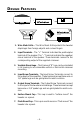
D ESIGN F EATURES 1 7 6 ® ® 2 3 ® ® ACTIVE TWEETER PROTECTION RFA-142x ® 2 4 5 1. Wire Mesh Grille – The Wire Mesh Grille protects the tweeter diaphragm from foreign objects and curious fingers. 2. Input Terminals – The “+” Terminal indicates the positive/plus terminal of the speaker. The “–” Terminal indicates the negative/ minus terminal of the speaker. These terminals connect to the corresponding output of the supplied crossover. 3.
I NSTALLATION C ONSIDERATIONS Tools Needed The following is a list of some of the tools necessary for the installation of your speakers. Power Drill with assorted bits Tape Measure Voltmeter #2 Phillips Screwdriver Hole Saw (2") General 1. For safety, disconnect the negative lead from the battery prior to beginning the installation. 2. Never run wires underneath the vehicle. Running the wires inside the vehicle provides the best protection. 3. Avoid running wires over or through sharp edges.
M OUNTING L OCATION A solid front stage with a good image is one of the most difficult tasks to achieve in a vehicle. No car has the optimum listening environment. This makes proper sound staging very difficult to accomplish. Most speakers tend to be placed where they will fit easily, as opposed to where they can perform the best. The mounting location of your speakers will have a great effect on the sound quality of your stereo system.
• Sound radiated from a “point source” has the most optimum stereo imaging because the separation of the acoustical centers between the midrange and tweeter for each channel is at the optimum. Figure 2-A describes a horizontal speaker alignment. In a closed environment such as an automobile, horizontal speaker alignment can cause severe amplitude and phase differences which will degrade not only the imaging, but also the frequency response.
Surface Mount Tweeter (Method #1) ® Mounting Baffle Mounting Screw Surface Mount Baseplate Surface Mount Cup Front View Exploded View (twist clockwise to lock) • Use when mounting tweeter to a solid surface (metal, wood, etc.
® Flush Mount Tweeter Mounting Bolt Mounting Baffle Nut 2" Cutout Flush Mount Baseplate Bracket Flush Mount Cup Rear View (twist clockwise to lock) Exploded View Crossover Connections HP CROSSOVER LP CROSSOVER TWEETER PROTECTION TWEETER (Rear View) ® “+” – + Input OUTPUT FROM AMPLIFIER – + – + Mid Output – + Tweeter Output • Striped Wire indicates “+” terminal of tweeter • Be Sure to Maintain Speaker Polarity – 11 – “+”Dot ® I N S T A L L A T I O N
® Bandpassing the Midrange RFA-142x Midrange Output + – – + 400µf capacitor • To bandpass the midrange, it is necessary to add a 400µf capacitor in series with the speaker Tweeter Level Matching Cut jumper wire for –3dB • Factory set tweeter level is –0dB • Cut jumper wire on bottom of crossover to reduce tweeter level by –3dB – 12 – ® I N S T A L L A T I O N
® Horizontal Logo Mounting ® ® ® ACTIVE TWEETER PROTECTION RFA-142x ® ACTIVE TWEETER PROTECTION RFA-142x ® ® • Configure logo into desired position and snap into place ® ® ® ® ACTIVE TWEETER PROTECTION RFA-142x ® ® ACTIVE TWEETER PROTECTION RFA-142x Vertical Logo Mounting • Configure logo into desired position and snap into place – 13 – ® I N S T A L L A T I O N
TROUBLESHOOTING Symptom No sound from speakers Diagnosis Remedy Wires between amplifier, crossover and speakers not connected properly. Check and repair or replace wiring as needed. Amplifier has no output. Check system with known working amplifier and repair or replace as needed. Speaker wires are shorted to each other or to the chassis of the vehicle. Check for shorts in the wiring with a volt/ohm meter and repair or replace wires as needed Speakers are blown.
Symptom Engi ne Noise from One or More Speakers Diagnosis Remedy Speaker wires shorted to chassis of vehicle. Check for shorts in the wiring with a volt/ohm meter and repair or replace wires as needed. Speaker wires are routed near radiated noise source. (Power cables, vehicle computers, etc.) Re-route speaker wiring away from noise sources. (Refer to the Installation Considerations section of this manual.) Crossover is mounted near radiated noise source. (Power cables, vehicle computers, etc.
S P E C I F I C AT I O N S Model RFA-14 Freq. Response RFA-44 3kHz-20kHz 3kHz-20kHz RFA-54 RFA-64 44Hz-6kHz 39Hz-6kHz Power Handling (RMS) 50 Watts* 30 Watts 50 Watts 80 Watts Nom. Impedance 4Ω 4Ω 4Ω 4Ω 92dB 86dB 86dB 89dB Fs (Hz) 2000Hz 94Hz 44Hz 39Hz Mounting Diameter Refer to drawing 4" (101.6mm) 47⁄8" (122.8mm) 55⁄8" (142.9mm) Mounting Depth Refer to drawing 1 (45.2mm) 25⁄8" 66.7mm) 33⁄32" (78.
L IMITED W A R R A N T Y I N F O R M AT I O N Rockford Corporation offers a limited warranty on Rockford Fosgate products on the following terms: • Length of Warranty 1 year on speakers 3 years on electronics 2 years on source units 30 days on speaker B-stock (receipt required) 90 days on electronic B-stock (receipt required) • What is Covered This warranty applies only to Rockford Fosgate products sold to consumers by Authorized Rockford Fosgate Dealers in the United States of America or its possessions.
A A TI N T M O ER IO R N T N FO IN A L IN – 18 –
LEA DETENIDAMENTE LAS SIGUIENTES INSTRUCCIONES DE INSTALACIÓN DEL PRODUCTO. I NTRODUCCIÓN Este manual contiene información sobre la construcción, installación y funcionamiento de los sistemas Punch AUDIOphile. Le recomendamos que conserve el manual para futuras consultas. Es preferible que la instalación de sistema Punch AUDIOphile sea realizada por un distribuidor autorizado Rockford Fosgate. Si prefiere realizar la instalación usted mismo, asegurese de leer el manual en su totalidad antes de comenzar.
Mounting Baffle Mounting Bolt Nut Surface Mount Baseplate Surface Mount Cup Seccion Vista Frontal (Gire en el sentido contrario a las agujas del reloj para fijar) • Use la base extra cuando monte el tweeter en una superficie que necesite refuerzo. Montaje Empotrado Mounting Bolt Mounting Baffle Nut 2" Cutout Bracket Flush Mount Baseplate Flush Mount Cup Vista de Atrás Seccion (Gire en el sentido contrario a las agujas del reloj para fijar) – 20 – E SPAÑOL 2.
® Paso Banda Para del Medio RFA-142x Midrange Output + – – + 400µf capacitor • Para hacer un paso banda para el medio se ha de añadir un condensador de 400µf en serie con el altavoz Ajuste de Nivel del Tweeter (Vista inferior del RFA-142x) Cut jumper wire for –3dB • El ajuste de origen es –0dB • Corte el hilo en la parte inferior del tweeter para una reduccion del nivel del tweeter de –3dB – 21 – ® I N S T A L L A T I O N
Veuillez lire les instrucitons suivantes pour l'installation de ces produits. I NTRODUCTION Ce manuel contient des informations sur les caractéristiques et l'installation des systèmes Punch AUDIOphile. Nous vous proposons de garder ce manuel pour toute référence future. EMPLACEMENT DE MONTAGE • Pour bénéficier d'une harmonie maximum entre le médium et l'aigu l'éloignement entre ces deux hautparleurs devrait être de moins de 5 cm entre les 2 chassis.
3. Retirer l'anneau. Percer les trous des vis en utilisant une mèche de 3mm. 4. Faire passer les fils dans le trou central. 5. Installer les clips (clips Tinnerman) sur les trous des vis. Placer l'anneau de montage au-dessus du trou central. 6. Connecter les fils au haut-parleur en respectant les polarités. Eloigner les fils de toute partie tranchante ou mobile du véhicule. 7. Placer le haut-parleur au-dussus du trou central. Visser le haut-parleur dans son emplacement.
Bandpassing the Midrange RFA-142x Midrange Output + – – 400µf capacitor + • To bandpass the midrange, it is necessary to adda 400µf capacitor in series with the speaker Compensation du Niveau Aigu Vue d'en bas du PCH-142x jumper Coupez Cut le pontage au for –3dB verso duwire filtre pour –3dB • Le niveau de défaut est de –0dB • Coupez le pontage au verso du filtre our atténuer l'aigu de 3dB.
Die folgende Bedienungsanleitung soll Ihnen beim Einbau eine Hilfestellung geben. E NLEITUNG Diese Bedienungsanleitung enthält Informationen für den Gebrauch und Einbau des Punch AUDIOphile Systems. Wire empfehlen, sie auch für Fragen in der Zukunft sorgfältig aufzubewahren. Es ist empfehlenswert, sich das Punch AUDIOphile System von einem Autorisierten Rockford Fosgate Fachhändler einbauen zu lassen.
3. Nehmen Sie den Ring wieder ab und bohren Sie dann, mit einem passenden Bohrer, die Schraubenlöcher vor. 4. Führen Sie das Kabel durch das Loch. 5. Stecken Sie die Schraubenships über die Schraubenlöcher. Plazieren sie den Montagering über dem Loch. 6. Schlieβen Sie die Lautsprecherkabel an. Kontrollieren Sie, ob die Polarität stimmt. Stellen Sie sicher, daβ das Lautsprecherkabel an keinen scharfen oder sich bewegenden Teilen anliegt. 7. Plazieren Sie den Lautsprecher im Loch und befestigen ihn.
Bandpassing the Midrange RFA-142x Midrange Output + – – 400µf capacitor + • To bandpass the midrange, it is necessary to adda 400µf capacitor in series with the speaker Tweeter Level Matching Bottom view of RFA-142x Cut jumper Cut jumper wire for –3dB wire for –3dB • Factory set tweeter level is –0dB • Cut jumper wire on bottom of crossover to reduce tweeter level by –3dB – 27 –
Leggere le istruzioni seguenti prima dell'installazione del prodotto. I NTRODUZIONE Questo manuale fornisce informazioni sulle caratteristiche e sul installazione dei sistemi Punch AUDIOphile. Vi suggeriamo di conservare questo manuale come riferimento futuro. Raccomandiamo fortemente che is sistema sia installato dal vostro rivenditore Rockford Fosgate. Se scegliete di procedere con l'installazione da soli, leggete attentamente tutto il manuale prima di proseguire.
3. Togliete l'anello e forate il pannello con una puna da 3,5mm. 4. Passate i cavi attraverso il foro. 5. Posizionate le clips di fissaggio sopra i fori delle viti e l'anello della griglia sopra il foro dell'altoplarlante. 6. Collegate i cave assicurandovi di osservare la corretta polarità. Assicuratevi di mantenere i cavi lontano da parti in movimento o strutture taglienti. 7. Posizionate l'altoparlante nel foro ed avvitatelo. Assicuratevi di non piegare il cestello dell'altoparlante. 8.
Bandpassing the Midrange RFA-142x Midrange Output + – – 400µf capacitor + • To bandpass the midrange, it is necessary to adda 400µf capacitor in series with the speaker Tweeter Level Matching Bottom view of RFA-142x Cut jumper Cut jumper wire for –3dB wire for –3dB • Factory set tweeter level is –0dB. • Cut jumper wire on bottom of crossover to reduce tweeter level by –3dB.
MADE IN THE USA This product is designed, developed and assembled in the USA by a dedicated group of American workers. The majority of the components used in the construction of this product are produced by American companies. However, due to the global nature of their manufacturing facilities and the loudspeaker parts industry in general, some parts may be manufactured in other countries. Rockford Fosgate Rockford Corporation 546 South Rockford Drive Tempe, Arizona 85281 U.S.A. In U.S.A.