Installation & Operation Installation et fonctionnement Instalación y funcionamiento Einbau und Betrieb Installazione e funzionamento
INTRODUCTION Dear Customer, Congratulations on your purchase of the world's finest brand of car audio amplifiers. At Rockford Fosgate we are fanatics about musical reproduction at its best, and we are pleased you chose our product.Through years of engineering expertise, hand craftsmanship and critical testing procedures, we have created a wide range of products that reproduce music with all the clarity and richness you deserve.
GETTING STARTED Welcome to Rockford Fosgate! This manual is designed to provide information for the owner, salesperson and installer. For those of you who want quick information on how to install this product, please turn to the Installation Section of this manual. Other information can be located by using the Table of Contents.We, at Rockford Fosgate, have worked very hard to make sure all the information in this manual is current.
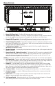
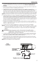
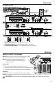
DESIGN FEATURES 1 2 4 3 5 9 6 7 8 10 11 12 8 9 10 11 13 12 14 15 16 1. Power LED (Top of unit) – This Blue LED illuminates when the unit is turned on. 3. Protect LED (Top of unit) – This Yellow LED illuminates if a short circuit or too low of an impedance is detected at the speaker connections.The amplifier will automatically shut down if this occurs. 2. 4. 5. 6. 7.
DESIGN FEATURES 14. RCA Pass-Thru Jack – This Pass-Thru provides a convenient source for daisy-chaining an additional amplifier without running an extra set of RCA cables from the front of the vehicle to the rear amplifier location. 15. Remote Terminal – This heavy duty, nickel-plated wire connector will accept wire sizes from 8 AWG to 16 AWG.This terminal is used to remotely turn-on and turn-off the amplifier when +12V DC is applied. 16.
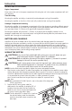
INSTALLATION MOUNTING LOCATIONS Engine Compartment Never mount this unit in the engine compartment. Mounting the unit in the engine compartment will void your warranty. Trunk Mounting Mounting the amplifier vertically or inverted will provide adequate cooling of the amplifier. Mounting the amplifier on the floor of the trunk will provide the best cooling of the amplifier.
3. 4. 5. INSTALLATION Trim the RED wire (power cable) within 18" of the battery and splice in a inline fuse holder (not supplied). See Specifications for the rating of the fuse to be used. DO NOT install the fuse at this time. Strip 1/2" from the battery end of the power cable and crimp a large ring terminal to the cable. Use the ring terminal to connect to the battery positive terminal.
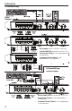
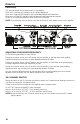
INSTALLATION 2-Channel Wiring Mono Bridged • RCA Inputs connect to FRONT inputs only. • Gain (Front & Rear) - is set independently to suit application. • • 2/4 CH. SWITCH up position to set to 2 CH. Crossover (Front & Rear) - is set independently to suit application. 4-Channel Wiring Stereo Bridged • 2/4 CH. SWITCH down position to set to 4 CH. • Crossover (Front & Rear) - is set independently to suit application. • 8 Gain (Front & Rear) - is set independently to suit application.
INSTALLATION 4-Channel Wiring • 2/4 CH. SWITCH down position to set to 4 CH. • Crossover (Front & Rear) - is set independently to suit application. • Gain (Front & Rear) - is set independently to suit application. OPERATION REMOTE PUNCH EQ (Optional) NOTE:Previous (prior to 2007) Punch Bass and Para-Punch remotes will not work with these amplifiers. NOTE: Use the instructions that came with the remote for a variety of mountings that fit your preference. Quick Install 1.
OPERATION PUNCH EQ This works along with the crossover switch on the amplifier. When set to Low-Pass (LP) operation, this is a variable Bass Boost. When set to High-Pass (HP) operation, this is a variable Mid-Bass and Treble Boost. When set to All Pass (AP) operation, both the Bass and Treble frequencies are boosted. Set this to your personal preference while listening to the system. NOTE: Connecting the optional remote overrides the Punch EQ rear channel control on the amplifier.
OPERATION ADJUSTING GAIN Do the following individually for each channel. To adjust the gain setting, turn the amplifier gains all the way down (counter-clockwise).Turn the source unit volume up until distortion is audible and then turn it down a bit until the distortion is inaudible.This will be about all the way up on most source units. Next, increase the amplifier gain setting until adequate volume is achieved. NOTE:Best signal to noise and dynamic range are realized with the gain at minimum.
TROUBLESHOOTING 2. Bypass any and all electrical components between the stereo and the amplifier(s). Connect stereo directly to input of amplifier. If noise goes away the unit being bypassed is the cause of the noise. OR 3. Remove existing ground wires for all electrical components. Reground wires to different locations. Verify that grounding location is clean, shiny metal free of paint, rust etc. OR 4.
LIMITED WARRANTY INFORMATION Rockford Corporation offers a limited warranty on Rockford Fosgate products on the following terms: Length of Warranty Speakers, Signal Processors and PUNCH Amplifiers – 1 Year POWER Amplifiers – 2 Years Any Factory Refurbished Product – 90 days (receipt required) What is Covered This warranty applies only to Rockford Fosgate products sold to consumers by Authorized Rockford Fosgate Dealers in the United States of America or its possessions.
INTRODUCTION Français Cher client, Toutes nos félicitations pour avoir acheté la meilleure marque d'amplificateurs pour automobile. Chez Rockford Fosgate nous sommes des mordus de la reproduction musicale à son meilleur. C’est pourquoi nous sommes heureux que vous ayez choisi notre produit. Des années d’expertise en ingénierie, de savoir-faire et d’essais poussés nous ont permis de créer une vaste gamme de produits capables de reproduire toute la clarté et la richesse musicales que vous méritez.
AVANT DE COMMENCER Bienvenue à Rockford Fosgate ! Ce manuel vise à informer le propriétaire, le vendeur et l’installateur de l’appareil. Si vous désirez apprendre rapidement comment installer ce produit, consultez la section Installation du manuel. Reportez-vous à la Table des matières pour d’autres informations. Nous nous efforçons de faire en sorte que toutes les informations contenues dans ce manuel soient à jour.
Français PARTICULARITÉS TECHNIQUES 1 2 4 3 5 9 6 7 8 10 11 12 8 9 10 11 13 12 14 15 16 1. DEL d'alimentation (au-dessus de l'appareil) – Cette DEL bleue s'illumine lorsque l'appareil est allumé. 3. DEL de protection (au-dessus de l'appareil) - Cette DEL jaune s'illumine si un court-circuit ou une impédance trop basse est détecté au niveau des connexions de haut-parleur. L'ampli s'éteint automatiquement si cela se produit. 2. 4. 5. 6. 7.
PARTICULARITÉS TECHNIQUES 14. Extension ampli RCA – L'extension ampli permet de connecter en guirlande un second ampli en évitant d'acheminer des câbles RCA supplémentaires de l'avant du véhicule vers l'emplacement de l'ampli arrière. 15. Bor6e de télécommande - Ce connecteur nickelé de haute qualité accepte les fils de calibre AWG 8 à 16. Cette borne sert à allumer et éteindre l'amplificateur à distance lorsqu'une tension de +12 V c.c. y est appliquée. 16.
INSTALLATION Français EMPLACEMENTS DE MONTAGE Compartiment moteur Ne montez jamais cet appareil dans le compartiment moteur. Cela entraînerait l’annulation de la garantie. Montage dans le coffre Un montage vertical de l'ampli assure un refroidissement adéquat. Le montage de l'ampli sur le plancher du coffre assure un refroidissement optimal. Le montage de l'ampli à l'envers, sur la tablette arrière, assure un refroidissement adéquat.
2. INSTALLATION Préparez le fil ROUGE (câble d'alimentation) qui devra être relié à l'ampli en dénudant 7/8 po (2,2 cm) de son extrémité. Insérez la partie dénudée dans la borne B+, puis fixez le fil en vissant la vis sans tête. REMARQUE : Le câble B+ DOIT comporter un fusible à 18 po (45,7 cm) ou moins de la batterie du véhicule. Installez le porte-fusible sous le capot et assurez-vous que les connexions sont étanches. 3. 4. 5.
INSTALLATION Français Câblage à 2 voies Ponté mono • • • • Entrées RCA connectées à l'AVANT seulement. COMMUTATEUR DE CANAL 2/4 Relever pour régler sur 2 canaux. Gain (avant et arrière) - Réglé de façon indépendante selon l'application. Filtre passif (avant et arrière) - Réglé de façon indépendante selon l'application. Câblage à 4 voies Ponté stéréo • • • 8 COMMUTATEUR DE CANAL 2/4 - Abaisser pour régler sur 4 canaux Gain (avant et arrière) - Réglé de façon indépendante selon l'application.
INSTALLATION Câblage à 4 voies • • • COMMUTATEUR DE CANAL 2/4 - Abaisser pour régler sur 4 canaux Gain (avant et arrière) - Réglé de façon indépendante selon l'application. Filtre passif (avant et arrière) - Réglé de façon indépendante selon l'application. FONCTIONNEMENT TÉLÉCOMMANDE D'ÉGALISEUR PUNCH (en option) REMARQUE : Les modèles précédents (antérieurs à 2007) de télécommandes de basses Punch et Para-Punch ne fonctionneront pas avec ces amplificateurs.
FONCTIONNEMENT Français ÉGALISEUR PUNCH Esto funciona junto con el interruptor de cruce en el amplificador. Cuando está ajustado para la operación en Pasa Bajos (Low Pass, LP) esto es un Refuerzo de Bajos variable. Cuando está ajustado para la operación en Pasa Altos (High Pass, HP) esto es un Refuerzo de Bajos Medianos y Agudos variable. Cuando está ajustado para la operación en Todos Pasan (All Pass,AP), se refuerzan ambas frecuencias Bajas y Altas.
FONCTIONNEMENT RÉGLAGE DU GAIN Procédez de la manière suivante pour chaque voie séparément. Pour régler le gain, tournez le bouton de gain de l'ampli vers son niveau le plus bas (sens anti-horaire).Augmentez le volume de la source audio jusqu'à produire une distorsion audible, puis baissez-le jusqu'à ce que la distorsion devienne inaudible. Cela correspondant généralement au maximum du volume sur la plupart des unités source.Augmentez ensuite le gain de l'ampli jusqu'à ce que le volume soit adéquat.
DÉPANNAGE Français 2. Contournez tous les composants électriques situés entre la stéréo et l’ampli.Connectez la stéréo directement à l’entrée de l’ampli.Si le bruit disparaît,l’unité contournée est la cause du bruit. OU 3. Retirez les fils de masse de tous les composants électriques.Branchez de nouveau les fils à la masse,mais à des emplacements différents.Vérifiez que ceux-ci sont propres,que le métal est brillant sans trace de peinture,ni rouille,etc. OU 4.
INFORMATIONS SUR LA GARANTIE LIMITÉE Rockford Corporation offre une garantie limitée sur les produits Rockford Fosgate selon les termes suivants : Durée de la garantie Sources audio, haut-parleurs, processeurs de signaux et amplificateurs PUNCH — 1 an Amplificateurs POWER — 2 ans Tout produit remis à neuf en usine — 90 jours (reçu obligatoire) Couverture Cette garantie s'applique uniquement aux produits Rockford Fosgate vendus à des consommateurs par des distributeurs agréés Rockford Fosgate, aux États
INTRODUCCIÓN Estimado cliente, Español Felicitaciones por su compra de la mejor marca del mundo de amplificadores para automóviles. En Rockford Fosgate somos fanáticos de la mejor reproducción musical y estamos agradecidos de que haya escogido nuestro producto. Con muchos años de experiencia en ingeniería, conocimiento del oficio y procedimientos de prueba críticos, hemos creado una amplia gama de productos para reproducción musical con toda la claridad y la riqueza que usted merece.
INICIO ¡Bienvenidos a Rockford Fosgate! Este manual ha sido creado para proporcionarle información al dueño, vendedor y técnico de instalación. Para quienes desean información rápida sobre cómo instalar este producto, por favor vean la Sección Instalación de este manual. El resto de la información puede encontrarse usando el Índice de Materias. Nosotros, en Rockford Fosgate hemos trabajado arduamente para asegurarnos que toda la información de este manual esté actualizada.
CARACTERÍSTICAS DEL DISEÑO 1 2 4 Español 3 5 1. 2. 3. 4. 5. 6. 7. 9 10 11 9 10 11 LED de alimentación (Parte superior de la unidad) – Este LED azul se ilumina cuando se enciende la unidad. 6 7 8 12 8 13 12 14 15 16 LED de temperatura (Parte superior de la unidad) – Este LED rojo se ilumina si el amplificador llega a la tercera etapa de protección térmica. El amplificador se apagará para enfriarse si esto sucede.
CARACTERÍSTICAS DEL DISEÑO 13. Interruptor de 2/4 canales - Si se coloca este interruptor en la posición 2CH., conmuta las entradas a un modo de 2 canales, permitiendo la conexión sólo a las entradas delanteras con una salida de 4 canales. 14. Enchufes RCA de Paso Directo - El paso directo brinda una fuente conveniente para conectar un amplificador adicional en cadena, sin tener que conectar otro juego de cables RCA desde el frente del vehículo hasta el punto del amplificador trasero. 15.
INSTALACIÓN LUGARES DE MONTAJE Compartimento del motor Nunca instale esta unidad en el compartimento del motor. Instalar la unidad en el compartimento del motor anulará su garantía. Instalación en el maletero Español El montaje vertical del amplificador proporcionará suficiente enfriamiento para el mismo. El montaje del amplificador en el piso del maletero proporcionará el mejor enfriamiento del mismo.
INSTALACIÓN NOTA: Se DEBE instalar un fusible en el cable B+ a 18 pulg. (45,7 cm) o menos de distancia de la batería del vehículo. Instale el porta-fusibles abajo del capó / cofre y asegúrese de que las conexiones sean herméticas. 3. 4. 5. Recorte el cable ROJO (cable de alimentación) a menos de 18 pulg. (45,7 cm) de la batería y empálmelo en un portafusibles en línea. Consulte en las especificaciones de la capacidad del fusible que debe usar. NO instale el fusible en este momento.
INSTALACIÓN Español Cableado de 2 canales Mono ponteado • • • • Las entradas RCA sólo se conectan a las entradas DELANTERAS. INTERRUPTOR 2/4 CANALES en la posición hacia arriba para configurar para 2 canales. Ganancia (adelante y atrás) – se ajusta independientemente de acuerdo a la aplicación. Cruce (adelante y atrás) – se ajusta independientemente de acuerdo a la aplicación.
INSTALACIÓN Cableado de 4 canales • • • INTERRUPTOR 2/4 CANALES en la posición hacia abajo para configurar para 4 canales. Ganancia (adelante y atrás) – se ajusta independientemente de acuerdo a la aplicación. Cruce (adelante y atrás) – se ajusta independientemente de acuerdo a la aplicación. FUNCIONAMIENTO REMOTE PUNCH EQ (Opcional) NOTA: Los controles remotos Punch Bass y Para-Punch previos (anteriores a 2007) no funcionarán con estos amplificadores.
FUNCIONAMIENTO PUNCH EQ Español Esto funciona junto con el interruptor de cruce en el amplificador. Cuando está ajustado para la operación en Pasa Bajos (Low Pass, LP) esto es un Refuerzo de Bajos variable. Cuando está ajustado para la operación en Pasa Altos (High Pass, HP) esto es un Refuerzo de Bajos Medianos y Agudos variable. Cuando está ajustado para la operación en Todos Pasan (All Pass,AP), se refuerzan ambas frecuencias Bajas y Altas.
FUNCIONAMIENTO AJUSTE DE GANANCIA Haga lo siguiente individualmente para cada canal. Para ajustar la ganancia, gire las ganancias del amplificador totalmente hacia abajo (sentido contra horario). Suba el volumen de la unidad de origen hasta que pueda escuchar la distorsión y luego gire hacia abajo un poco hasta que no se pueda escuchar la distorsión. Esto será hasta arriba en la mayoría de las unidades fuentes. Luego, aumente el ajuste de ganancia del amplificador hasta que se obtenga un volumen adecuado.
SOLUCIÓN DE PROBLEMAS 2. Desvíe cualquiera y todos los componentes eléctricos entre el estéreo y los amplificadores.Conecte el estéreo directamente a la entrada del amplificador.Si el ruido desaparece el componente que está siendo desviado es la causa del ruido. O 3. Quite los cables a tierra existentes de todos los componentes eléctricos.Vuelva a conectarlos a tierra en lugares diferentes.Verifique que el sitio de conexión a tierra esté limpio,que sea metal brilloso sin pintura,óxido,etc.
INFORMACIÓN SOBRE LA GARANTÍA LIMITADA Rockford Corporation ofrece una garantía limitada para los productos Rockford Fosgate bajo los siguientes términos: Duración de la garantía Unidades Fuente, altavoces, procesadores de señales y amplificadores PUNCH—1 año Amplificadores POWER—2 años Cualquier producto de fábrica restaurado—90 días (comprobante de compra requerido) Qué está cubierto Esta garantía se aplica solamente a los productos Rockford Fosgate vendidos a consumidores por Concesionarios Autorizad
EINLEITUNG Liebe Kundin, lieber Kunde, wir gratulieren Ihnen zu Ihrem Kauf von Autoaudioverstärkern der besten Marke weltweit.Wir bei Rockford Fosgate sind Fanatiker, wenn es um die beste musikalische Reproduktion geht, und freuen uns darüber, dass Sie unser Produkt gewählt haben. Durch jahrelange Ingenieurserfahrung, Handwerkskunst und kritische Testverfahren haben wir ein weites Spektrum an Produkten geschaffen, die die Musik mit aller Klarheit und Klangschönheit reproduziert, die Sie verdienen.
HIER GEHT’S LOS Willkommen bei Rockford Fosgate! Diese Anleitung bietet dem Besitzer, Verkäufer und Einbauenden Informationen. Kurzgefasste Informationen zum Einbau dieses Produkts finden sich im Abschnitt „Einbau“ dieser Anleitung. Andere Informationen können Sie mithilfe des Inhaltsverzeichnisses auffinden. Wir bei Rockford Fosgate haben uns sehr darum bemüht, dass alle in dieser Anleitung enthaltenen Informationen auf dem neusten Stand sind.
DESIGNCHARAKTERISTIKEN 1 2 4 Deutsch 3 5 1. 2. 3. 4. 5. 6. 7. 9 6 7 8 10 11 12 8 9 10 11 13 12 14 15 16 Betriebs-LED (Oberseite des Geräts) – Diese blaue LED leuchtet auf, wenn das Gerät betriebsbereit ist. Thermal-LED (Oberseite des Geräts) – Diese rote LED leuchtet auf, wenn der Verstärker die dritte Stufe des thermalen Schutzes erreicht hat.Wenn dies eintritt, schaltet sich der Verstärker zum Abkühlen aus.
DESIGNCHARAKTERISTIKEN 13. Zwei-/Vierkanalschalter - In der 2CH.-Position werden die Eingänge in einen Zweikanalmodus geschaltet. Dies ermöglicht einen Vierkanalausgang bei ausschließlicher Belegung der Fronteingänge. 14. RCA-Durchgangsausgänge – Der Durchgang bietet eine bequeme Quelle zum Daisy-Chaining eines zusätzlichen Verstärkers, ohne einen weiteren Satz von RCA-Kabeln vom vorderen Bereich des Wagens zum hinten befindlichen Verstärker zu verlegen. 15.
EINBAU BEFESTIGUNGSSTELLEN Motorraum Das Gerät darf nicht im Motorraum installiert werden. Ein solcher Einbau führt zum Verlust der Garantie. Einbau im Kofferraum Vertikale Befestigung des Verstärkers ermöglicht adäquates Kühlen des Verstärkers. Befestigung des Verstärkers auf dem Boden des Kofferraums bietet die beste Kühlung des Verstärkers. Befestigung des Verstärkers mit der Oberseite nach unten am Kofferraumdeckel ermöglicht adäquate Kühlung des Verstärkers.
EINBAU HINWEIS: 3. 4. 5. Das ROTE Kabel (Stromkabel) maximal 45 cm von der Batterie abisolieren und einen Inline-Sicherungshalter einspleißen. Der Bemessungsstrom der zu verwendenden Batterie ist in den Technischen Daten aufgeführt. Zunächst noch KEINE Sicherung einsetzen. Vom Batterieende des Stromkabels 13 mm Isolierung abziehen und einen großen, ringförmigen Stecker zur Befestigung am positiven Batteriepol an das Kabel crimpen. Die Sicherung noch nicht anbringen.
EINBAU Zweikanalverkabelung Deutsch Mono überbrückt • • • • RCA-Eingänge nur an den vorderen Eingängen anschließen. Zwei-/Vierkanalschalter für Zweikanalmodus nach oben legen. Lautstärke (vorn & hinten) – wird ja nach Anwendung unabhängig eingestellt. Crossover (vorn & hinten) - wird ja nach Anwendung unabhängig eingestellt. Vierkanalverkabelung Stereo überbrückt • • • 8 Zwei-/Vierkanalschalter für Vierkanalmodus nach unten legen.
EINBAU Vierkanalverkabelung • • • Zwei-/Vierkanalschalter für Vierkanalmodus nach unten legen. Lautstärke (vorn & hinten) – wird ja nach Anwendung unabhängig eingestellt. Crossover (vorn & hinten) - wird ja nach Anwendung unabhängig eingestellt. BETRIEB PUNCH-EQ-FERNBEDIENUNG (wahlweise) HINWEIS: HINWEIS: Vor 2007 hergestellte Modelle der Punch-Bass- und Para-Punch-Fernbedienungen können nicht mit diesen Verstärkern benutzt werden.
BETRIEB PUNCH EQ Deutsch Dies funktioniert gemeinsam mit dem Crossover-Schalter am Verstärker. Bei Einstellung auf Tiefpassbetrieb (LP) handelt es sich um eine variable Verstärkung der Bässe. Bei Einstellung auf Hochpassbetrieb (HP) handelt es sich um eine variable Verstärkung der Mitten und Höhen. Bei Einstellung auf Allpassbetrieb (AP) werden sowohl die Bässe als auch die Höhen verstärkt. Nehmen Sie Ihre persönliche Einstellung während des Zuhörens vor.
BETRIEB LAUTSTÄRKE (GAIN) EINSTELLEN Folgendes für jeden Kanal einzeln durchführen. Zur Einstellung der Lautstärke die Lautstärkeregler des Verstärkers ganz nach unten stellen (nach links drehen). Die Lautstärke des Source-Geräts erhöhen, bis eine Verzerrung hörbar ist, dann ein wenig verringern, bis die Verzerrung nicht mehr hörbar ist.An den meisten Source-Geräten bedeutet dies ganz nach oben.Als Nächstes die Lautstärkeeinstellung des Verstärkers erhöhen, bis eine adäquate Lautstärke erreicht ist.
FEHLERBESEITIGUNG 2. Alle elektrischen Komponenten zwischen der Stereoanlage und dem/den Verstärker(n) umgehen.Die Stereoanlage direkt am Verstärkereingang anschließen.Falls das Geräusch eliminiert ist,ist das umgangene Gerät die Ursache des Geräuschs. ODER 3. Die vorhandenen Erdungskabel aller elektrischen Komponenten entfernen.Die Kabel an anderen Stellen wieder erden.Prüfen, ob die Erdungsstelle sauberes,glänzendes Metall ist,das frei von Farbe,Rost usw.ist. ORER 4.
INFORMATIONEN ZUR BESCHRÄNKTEN GARANTIE Rockford Corporation bietet für Rockford Fosgate Produkte eine beschränkte Garantie zu folgenden Bedingungen: Laufzeit der Garantie Source-Geräte, Lautsprecher, Signalprozessoren und PUNCH-Verstärker – 1 Jahr POWER-Verstärker – 2 Jahre Alle werkseitig aufgearbeiteten Produkte – 90 Tage (Quittung erforderlich) Was gedeckt ist Diese Garantie erstreckt sich nur auf Rockford Fosgate Produkte, die von Rockford Fosgates Vertragshändlern an Verbraucher in den Vereinigten
INTRODUZIONE Egregio cliente, Congratulazioni per aver acquistato la miglior marca di amplificatori per auto a livello mondiale.Alla Rockford Fosgate, siamo fanatici per quanto riguarda la miglior riproduzione musicale e siamo compiaciuti che abbiate scelto il nostro prodotto. Dopo anni di competenza ingegneristica, maestria manuale e procedure di prova critica, abbiamo creato una larga gamma di prodotti che riproducono la musica con la limpidezza e la pienezza che vi meritate.
PRIMI PASSI Benvenuti alla Rockford Fosgate! Questo manuale è stato concepito per fornire ragguagli al proprietario, al rivenditore e all’installatore. Per coloro che desiderano informazioni rapide circa l’installazione di questo prodotto, vi preghiamo di consultare la sezione Installazione di questo manuale. Altri ragguagli sono disponibili attraverso l’Indice. Alla Rockford Fosgate, abbiamo fatto di tutto per assicurarci che tutte le informazioni contenute in questo manuale fossero d’uso corrente.
CARATTERISTICHE DEL DESIGN 1 2 4 3 Italiano 5 9 6 7 8 10 11 12 8 9 10 11 13 12 14 15 16 1. LED alimentazione (parte superiore dell'unità) – Questo LED blu si accende quando l'unità viene accesa. 3. LED di protezione (parte superiore dell'unità) – Questo LED giallo si accende se viene rilevato un corto circuito o un'impedenza troppo bassa ai collegamenti con i diffusori. In tal caso, l'amplificatore si spegne automaticamente. 2. 4. 5. 6. 7.
CARATTERISTICHE DEL DESIGN 13. Interruttore 2/4 canali - impostando questo interruttore sulla posizione 2CH (2 canali), si commutano gli ingressi alla modalità a 2 canali, permettendo il collegamento solo agli ingressi anteriori con un'uscita a 4 canali. 14.
INSTALLAZIONE POSIZIONAMENTO Scompartimento del motore Non montate mai questa unità nello scompartimento del motore. Ciò annullerà la vostra garanzia. Montaggio nel bagagliaio Se l'amplificatore viene montato in senso verticale, si ottiene un raffreddamento sufficiente per l'unità. Se l'amplificatore viene montato sul fondo del bagagliaio, si ottiene il migliore raffreddamento dell'unità.
INSTALLAZIONE NOTA:Il cavo B+ DEVE avere un fusibile a non più di 45,7 cm dalla batteria del veicolo. Installare il portafusibili sotto il cofano e verificare che i collegamenti siano a tenuta stagna. 3. 4. 5. Tagliare il cavo ROSSO (alimentazione) entro 45,7 cm dall'amplificatore e inserire un portafusibili in linea. Per informazioni sulla portata dei fusibili da usare, consultare il capitolo Specifiche. NON installare il fusibile a questo punto.
INSTALLAZIONE Cablaggio a 2 canali Italiano Mono in parallelo • • • • Gli ingressi RCA si collegano solo agli ingressi ANTERIORI. INTERRUTTORE 2/4 CANALI in posizione in alto per l'impostazione 2CH (2 canali). Guadagno (anteriore e posteriore) impostato in maniera indipendente a seconda dell'applicazione. Crossover (anteriore e posteriore) impostata in maniera indipendente a seconda dell'applicazione.
INSTALLAZIONE Cablaggio a 4 canali • INTERRUTTORE 2/4 CANALI in posizione in basso per l'impostazione 4CH (4 canali). • Crossover (anteriore e posteriore) - impostata in maniera indipendente a seconda dell'applicazione. • Guadagno (anteriore e posteriore) - impostato in maniera indipendente a seconda dell'applicazione. FUNZIONAMENTO EQUALIZZATORE PUNCH A DISTANZA (opzionale) NOTA: i vecchi comandi a distanza Punch Bass e Para-Bass (quelli prima del 2007) non funzioneranno con questi amplificatori.
FUNZIONAMENTO EQUALIZZATORE PUNCH Italiano Questo funziona assieme all'interruttore di crossover sull'amplificatore. Quando è impostato su operazione Low-Pass (LP), questo rappresenta un valore variabile di aumento dei bassi. Quando è impostato su operazione High-Pass (HP), questo rappresenta un valore variabile di aumento dei bassi intermedi e dei toni acuti. Quando è impostato su operazione All Pass (AP), sia le frequenze dei bassi che quelle dei toni acuti sono aumentate.
FUNZIONAMENTO REGOLAZIONE DEL GUADAGNO Eseguire le seguenti operazioni separatamente per ciascun canale. Per regolare l'impostazione per il guadagno, abbassare completamente i guadagni per l'amplificatore (ruotando in senso antiorario).Alzare il volume dell’unità di fonte finché la distorsione non diventi udibile, e poi abbassarlo finché la distorsione non sia più udibile. Nella maggior parte delle unità, ciò avviene quasi al volume massimo.
INDIVIDUAZIONE/RIPARAZIONE GUASTI Procedura 5:Controllate l’amplificatore se si verificasse un rumore eccessivo a livello del motore. 1. Fate scorrere tutti i fili che portano segnali (RCA,cavi degli altoparlanti) lontano dalla tensione e dai fili della messa a terra. OPPURE 2. Bipassate tutte le componenti elettriche tra il sistema stereofonico e l’amplificatore(i).Collegate il sistema stereofonico direttamente all’entrata dell’amplificatore.
INFORMAZIONI INERENTI ALLA GARANZIA LIMITATA La Rockford Corporation offre una garanzia limitata sui prodotti della Rockford Fosgate alle seguenti condizioni: Lunghezza della garanzia Unità di fonte, altoparlanti, elaboratori di segnali e amplificatori PUNCH — 1 anno Amplificatori POWER — 2 anni Prodotti rimessi a nuovo dalla fabbrica — 90 giorni (è necessaria la ricevuta) Ciò che è coperto dalla garanzia Questa garanzia è solamente applicabile ai prodotti della Rockford Fosgate venduti a clienti da par
Italiano NOTAS 14
NOTAS 15
Rockford Fosgate Rockford Corporation 600 South Rockford Drive Tempe, Arizona 85281 U.S.A. In U.S.A., (480) 967-3565 - Customer Service 1-800-669-9899 www.rockfordfosgate.com 12/2008 B.M. 01/2009 E.R.