USER'S MANUAL May be covered by one or more of the following: U.S. Patents #4538297, 4647876, 4696044, 4745309, 4881047, 4893099, 5124657, 5263091, 5268527, 5319713, 5333201, 5402498, 5493617 and 5638452. Other patents pending. Foreign patents pending.
Your MultiValve™ has been tested and complies with the following Standards and Directives as set forth by the European Union: Council Directive(s): 89/336/EEC Electromagnetic Compatibility Standard(s): EN55013, EN50082-1 This means that this product has been designed to meet stringent guidelines on how much RF energy it can emit, and that it should be immune from other sources of interference when properly used.
Contents 1. Introduction .......................................................................................... 1 2. Quick Setup .......................................................................................... 3 3. Front Panel ........................................................................................... 4 4. Rear Panel ............................................................................................ 6 5. Connections .....................................................
1. Introduction Congratulations on your purchase of the Rocktron MultiValve™ guitar effects processor! The MultiValve™ is a 24-bit DSP processor providing tube warmth to a host of high quality digital effects, as well as a number of practical features to enhance any guitar rig. • Audio Glassics 12AX7 tube, which can be inserted into the signal path on any preset, with 2 gain settings for added tube warmth.
PRECAUTIONS NOTE: IT IS VERY IMPORTANT THAT YOU READ THIS SECTION TO PROVIDE YEARS OF TROUBLE FREE USE. THIS UNIT REQUIRES CAREFUL HANDLING. All warnings on this equipment and in the operating instructions should be adhered to and all operating instructions should be followed. Do not use this equipment near water. Care should be taken so that objects do not fall and liquids are not spilled into the unit through any openings.
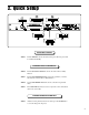
2. Quick Setup SELECTING A PRESET STEP 1 Turn the PRESET control to select the desired preset. The new preset will be recalled automatically. CHANGING PRESET PARAMETERS STEP 2 Turn the FUNCTION SELECT control to the desired effect or utility function. STEP 3 Turn the PARAMETER SELECT control to the parameter you wish to alter under the selected effect or utility function. STEP 4 Use the PARAMETER ADJUST control to select the new parameter value.
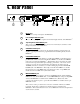
3. Front Panel 1 POWER switch 2 PRESET control This control scrolls through and instantly recalls the successive presets. 3 TAP DELAY/RATE button This button is used to select a new delay time or modulation rate based on the length of time occurring between two taps. See Section 7: "Tap Delay" for more information. 4 DISPLAY panel The DISPLAY panel provides 16 characters consisting of 14 segments each.
Front Panel Desccription 9 FUNCTION SELECT control This control allows access to each function of the MultiValve™ .
4. Rear Panel 1 INPUT jack This ¼" mono jack provides input to the MultiValve. 2 Left and Right OUTPUT jacks These ¼" mono jacks provide outputs from the left and right channels of the MultiValve™. 3 Tap Delay/Rate FOOTSWITCH jack This ¼" mono jack is provided for the connection of a momentary footswitch to control the Tap Delay feature of the MultiValve ™. 4 CHANNEL SWITCH jack This ¼" stereo jack can be connected to the channel switching footswitch jack on an amplifier or preamp.
Rear Panel Description 7 MIDI THRU/OUT jack This standard 5-pin DIN connector can be connected to the MIDI IN jack of another device via a standard MIDI cable. There are limitations to the number of devices that can be chained (or series connected) in this fashion. Note: 8 Inherently in MIDI there is a limit to the number of devices which can be chained together (connected in series).
5.
Using the MultiValve in a preamp effects loop 9
Connections Using the MultiValve with a mixing console 10
6. Operating Format The MultiValve provides 128 stored sounds called presets. Any of the 128 presets can be called up at any time via the front panel PRESET control (used to both select and recall a preset). The root of each preset’s sound is its configuration. The MultiValve provides two main effect configurations—the Classic configuration and the Rotary configuration. Each configuration provides a different selection of available effects.
Block Diagrams Classic Configuration Block Diagram 12
Block Diagrams Rotary Configuration Block Diagram 13
Functions and Parameter Descriptions MultiValve Functions and Parameter Descriptions Each MultiValve preset is divided into individual blocks called functions (such as "Mixer", "Reverb", etc.). Within each function is a set of controls which allow you to manipulate various aspects of that function. These controls are called parameters. The setting of each of the parameters determines the overall sound of each MultiValve preset.
Functions and Parameter Descriptions GLOBAL Function The first function displayed when turning the FUNCTION SELECT control is the Global function. The parameters provided in this function affect all presets (i.e. the settings stored for these parameters are the same for all presets).
Functions and Parameter Descriptions MIXER Function The next function displayed when turning the FUNCTION SELECT control is the Mixer function. The Mixer function parameters are included in all presets—regardless of which effects are active for the current preset - although the parameter values stored in this function are only for the currently recalled preset. This digital mixer allows you to control the signal levels pertaining to each preset’s configuration and stores those levels for each preset.
Functions and Parameter Descriptions TUBE MODE Function The Tube Mode function is accessible in all presets—regardless of the current configuration recalled. The Tube Mode function allows the input signal path to be routed through a high quality 12AX7 preamp tube to add a warm, vintage sound to the MultiValve effects used.
Functions and Parameter Descriptions HUSH Function The HUSH® function is accessible in all presets—regardless of the configuration currently recalled. HUSH is Hush Systems’ patented single-ended noise reduction system. The HUSH system contained in the MultiValve is a fully digital implementation of HUSH achieved through Digital Signal Processing (DSP), and is modeled after the latest HUSH design. The low level expander of the HUSH system operates like an electronic volume control.
Functions and Parameter Descriptions COMPRESSOR Function Compression is often used to maintain an even level when using clean tones, and is also used to increase sustain when using high gain distortion. The PARAMETER SELECT control will allow you to access each of the following Compressor parameters: COMPRESR I/O The COMPRESSOR I/O parameter determines whether the compression circuit is active or bypassed for the current preset.
Functions and Parameter Descriptions EQ Function 20 The EQ function provides full parametric control and allows you shape the tone of the input signal before it reaches each of the effect blocks. The PARAMETER SELECT control will allow you to access each of the following EQ parameters: EQ I/O The EQ I/O parameter determines whether the EQ circuit is active or bypassed for the current preset. BASS LVL The BASS LEVEL parameter allows you to cut or boost the low frequencies by up to 15dB.
Functions and Parameter Descriptions DELAY Function Delay provides a reproduction of the input signal, occurring at a prescribed time (usually expressed in milliseconds) following the input signal. The MultiValve provides two discrete delays (Delay 1 and Delay 2), each of which has its own set of parameters to determine its particular characteristics.
Functions and Parameter Descriptions SOURCE 2 This parameter is used to select whether the Source 2 input will be the VOICE 2 output from the previous effect in the signal chain or the direct signal. In configurations where there is no effect immediately preceding the delay, both Source 1 and Source 2 will be the direct signal. DLY HF DAMP The DELAY HIGH FREQUENCY DAMPING parameter controls the amount of high frequency content in the delayed and regenerated signals.
Functions and Parameter Descriptions REVERB Function ! Reverb is a multitude of echos spaced so close together that, to the human ear, seem as a single continuous sound. These echos gradually decrease in intensity until they are ultimately absorbed by the boundaries and obstacles within a room.
Functions and Parameter Descriptions TREMOLO Function 24 The Tremolo effect continuously varies the volume of the signal. The PARAMETER SELECT control will allow you to access each of the following Tremolo parameters: TREMOLO I/O The TREMOLO I/O parameter determines whether the tremolo circuit is active or bypassed for the current preset. LOCATION The LOCATION parameter determines whether the Tremolo is located Pre-Reverb or Post-Reverb.
Functions and Parameter Descriptions PHASER Function Phase shifting involves splitting the input signal into two signals, then shifting the phase of different frequencies of one signal before mixing it back with the original signal. The PARAMETER SELECT control will allow you to access each of the following Phaser parameters: PHASER I/O The PHASER I/O parameter determines whether the phase shift circuit is active or bypassed for the current preset.
Functions and Parameter Descriptions FLANGER Function Flanging splits the input signal into two individual delayed signals (Voice 1 and Voice 2), then modulating the delayed signals so that, when summed back with the direct signal, phase cancellations will occur at some frequencies while peaks in the response will occur at others.
Functions and Parameter Descriptions CHORUS Function The Chorus effect in the MultiValve is produced by detuning two delayed signals (Voice 1 and Voice 2), then modulating the detune effect so that the amount of pitch detune is constantly varying. Using different detune amounts, modulation rates, modulation depths and pan settings for each delayed signal will produce a greater perceived spaciousness.
Functions and Parameter Descriptions PITCH SHIFT Function Pitch Shifting is used to change the pitch of the input signal to produce a harmony note based on the input signal. The harmony voice may be of any fixed interval - up to one octave above the input signal to two octaves below - and is selected in 20-cent increments. Fine adjustment can be made in one cent (1/100th semitone) increments.
Functions and Parameter Descriptions PITCH SHIFT INTERVALS PARAMETER CORRESPONDING VALUE INTERVAL +1200 +1100 +1000 +900 +800 +700 +600 +500 +400 +300 +200 +100 0 -100 -200 -300 -400 -500 -600 -700 -800 -900 -1000 -1100 -1200 -1300 -1400 -1500 -1600 -1700 -1800 -1900 -2000 -2100 -2200 -2300 -2400 one octave Major 7th minor 7th Major 6th minor 6th perfect 5th diminished 5th perfect 4th Major 3rd minor 3rd Major 2nd minor 2nd Unison Major 7th minor 7th Major 6th minor 6th perfect 5th diminished 5th perfect
Functions and Parameter Descriptions AUTO PAN Function 30 The next function displayed when turning the FUNCTION SELECT control is the Auto Pan function. The Auto Pan effect auomatically pans between left and right when operating in stereo mode. (If operating in mono, the Auto Pan effect does not operate.
Functions and Parameter Descriptions ROTARY SPEAKER Function *For added versatility when using continuous control, the SLOW SPEED and FAST SPEED parameters cover the same range (0 to 100). Therefore, it is possible to have a SLOW setting which is faster than the FAST setting. The next function displayed when turning the FUNCTION SELECT control is the Rotary Speaker function. The Rotary Speaker effect simulates the classic rotating speaker popular with guitarists and keyboard players.
Functions and Parameter Descriptions SPEAKER SIMULATOR Function 32 The Speaker Simulator function provides a realistic approximation of a miked speaker cabinet for applications involving connecting the MultiValve directly to a mixing console, recording system or other full range system.
Functions and Parameter Ranges Master MultiValve Effects Parameter List (The actual functions displayed are configuration-dependent) Function Parameter Parameter Range GLOBAL OUTPUT HUSH OFFSET MUTE DIRECT Stereo, Mono -10dB to +30dB Out, In Out, In MIXER LEFT DIR RIGHT DIR EFFECT LEVEL DIRECT PHS DIR/EFF CHR DIR/EFF FLN DIR/EFF REV DIR/EFF VOLUME -∞ to +6dB -∞ to +6dB -∞ to +6dB Pre, Post Direct<0 to 100>Effect Direct<0 to 100>Effect Direct<0 to 100>Effect Direct<0 to 100>Effect 0 to 127 TUBE
Functions and Parameter Ranges Function Parameter Range DLY TIME1 FINE 1 DLY RGN 1 DELAY OUT 2 DLY PAN2 DLY TIME2 FINE 2 DLY RGN 2 D>SPILLOVER 0ms to 1000ms 0ms to 9ms -∞ to 0dB -∞ to 0dB Left<0 to 100>Right 0ms to 1000ms 0ms to 9ms -∞ to 0dB Off, On REVERB REV INPUT R-MIX EFF/DLY REVERB LVL REV DECAY REV HF DAMP R>SPILLOVER Muted, Active Effect<0 to 100>Delay -∞ to 0dB 0 to 99 0 to 99 Off, On TREMOLO TREMOLO I/O LOCATION TREM DPTH TREM RATE SHAPE TIME Out, In Pre-Rev, Post-Rev 0 to 100 0 to 254
Functions and Parameter Ranges Function Parameter Range CHORUS CHORUS I/O CRS OUT 1 CRS PAN 1 CRS DPTH 1 CRS RATE 1 CRS>DLY1 TIME1 CRS OUT 2 CRS PAN 2 CRS DPTH 2 CRS RATE 2 CRS>DLY2 TIME 2 Out, In -∞ to 0dB Left<0 to 100>Right 0 to 100 0 to 254 0ms to 148ms 32nd, 16th, 8th, Triplet, ¼, ½, or None -∞ to 0dB Left<0 to 100>Right 0 to 100 0 to 254 0ms to 148ms 32nd, 16th, 8th, Triplet, ¼, ½, or None PITCH SHIFT PITCH SH I/O PSHIFT OUT PS PAN PITCH FINE PS-SPEED Out, In -∞ to 0dB Left<0 to 100>Right -24
7. Operating the MultiValve Selecting a preset 1 Step 1 Turn the PRESET control to the desired preset you wish to recall. The selected preset will be recalled automatically.
Operating the MultiValve™ Changing preset parameters 4 Step 1 3 5 2 1 Turn the FUNCTION SELECT control to select the function heading which contains the parameter(s) you wish to change. SSSS REVERB SSSS Step 2 Turn the PARAMETER SELECT control to the specific parameter you wish to change. REV DECAY Step 3 Turn the PARAMETER ADJUST control to alter the parameter value. The LED above the STORE button will light, indicating that the preset has had a parameter altered from its stored value.
Operating the MultiValve™ Switching Channels on Amplifiers and Preamps via the MultiValve * The MultiValve™ allows you to switch channels on an amplifier or preamp by connecting a RTS cord from the "CHANNEL SWITCH" jack on the rear of the MultiValve™ to the "FOOTSWITCH" jack on the remote device(s). A single stereo-to-dual mono cord can also be used to connect from the MultiValve™ to two separate units. This allows for channel switching to be programmable (i.e.
Operating the MultiValve™ Step 4 Press the STORE button to save the condition of Channel Switch 1 (if changed). "STORED" will flash briefly on the display. STORED Step 5 Turn the PARAMETER SELECT control one step further clockwise to "CHAN SW 2". CHAN SW 2 Step 6 Use the PARAMETER ADJUST control to select the on/off condition of Channel Switch 2. When switched "ON", the channel which is connected to the Ring of the MultiValve™ CHANNEL SWITCH jack will be switched when the current preset is recalled.
Operating the MultiValve™ Editing a preset title 3 Step 1 5 2,4 1 To begin the Title Edit function, turn the FUNCTION SELECT control clockwise until the MultiValve™ displays "TITLE EDIT". SS TITLE EDIT SS Step 2 Turn the PARAMETER SELECT control clockwise to initiate the Title Edit mode. Turning this control will also select the character location to be edited. A flashing decimal will follow the character currently selected. 57 P.
Operating the MultiValve™ Step 5 After all the characters have been edited as needed, press the STORE button to save the new title memory. The MultiValve™ will flash "STORED" briefly. STORED Note: The STORE button must be pressed to save the new title. Exiting the Title Edit function before pressing the STORE button will erase any editing that was done in Title Edit. Also, after flashing "STORED", the MultiValve™ will remain in the Title Edit mode.
Operating the MultiValve™ Controller Assignments The Controller Assignment function allows for specific MultiValve™ adjustable parameters to be mapped (or assigned)* to a MIDI controller for real-time control by an expression pedal. The Controller Assignment option also lets you store an upper and lower parameter value limit which the controller cannot exceed.
Operating the MultiValve™ Step 3 Use the PARAMETER ADJUST control to select the controller number to be assigned to the PA-A parameter. Any number from 0 to 120 may be selected, as well as OFF (will not respond to MIDI control changes). Match the number selected for this parameter with the controller number on the MIDI transmitter. CTR A Step 4 7 After selecting the desired controller number, press the STORE button to save the number for the "CTR A" parameter.
Operating the MultiValve™ Note: Step 8 The MultiValve™ allows you to select an upper and lower value limit which the parameter cannot exceed. For example, if a parameter has a value range from -∞ to 0dB, yet you would like the range of the parameter to vary from only -12dB to -2dB, you may set a lower limit of -12 and an upper limit of -2 via the Upper and Lower Limit parameters.
Operating the MultiValve™ Step 12 Use the PARAMETER ADJUST control to select the lowest value which the parameter is not to fall below through MIDI control changes. LLIM A Step 13 -12 After selecting a value for the lower limit, press the STORE button to save it. "STORED" will flash briefly on the display. STORED Selecting a lower limit value that is greater than the upper limit value will invert the response of the controller - i.e.
Operating the MultiValve™ Copying MultiValve Presets, Titles and Controller Assignments The Copy function allows you to copy any preset, preset title or controller assignment into any other preset location instantly. 3 4 5 2 1 Copying presets: Step 1 Turn the FUNCTION SELECT control to "COPY". SSSS COPY SSSS Step 2 Turn the PARAMETER SELECT control one step clockwise to access the "PR> XX to >PR XX" parameter, as shown below.
Operating the MultiValve™ Step 6 After flashing "STORED", the MultiValve™ will display "COPY TITLE TOO?". This allows you to copy the title from the copied preset into the new location as well. To copy the title, press the STORE button a second time. "STORED" will flash briefly before the MultiValve™ displays the new preset number and title. STORED Turning the PARAMETER ADJUST control instead of pressing the STORE button allows you copy the title from the preset being copied to any other location.
Operating the MultiValve™ Step 5 Press the STORE button to copy the selected title into the selected preset location. "STORED" will flash briefly before displaying the preset title at its new location. STORED Copying controller assignments: Step 1 Turn the FUNCTION SELECT control to "COPY". SSSS COPY SSSS Step 2 Turn the PARAMETER SELECT control three steps clockwise to access the "CA> XX to >CA XX" parameter, as shown below.
Operating the MultiValve™ Tap Delay The MultiValve™ allows you to change the delay times and/or modulation rates for any given preset while you are playing two different ways: 1. By tapping the TAP DELAY/RATE button on the front panel of the MultiValve™, or 2. By tapping a momentary footswitch connected to the rear panel TAP DELAY/RATE FOOTSWITCH jack. 3. By using a Rocktron All Access™ in Remote mode with the MultiValve™ and tapping switch #15.
Operating the MultiValve Program Changes Program Changes allow for different MIDI program numbers to be assigned to MultiValve preset numbers. For example, MIDI program #58 can be mapped to MultiValve preset #34. Then, when program #58 is selected from a MIDI transmitting device (such as a Rocktron All Access foot controller), preset #34 will be recalled on the MultiValve. The Program Changes Map table is shipped from Rocktron at a one-to-one correspondance (i.e.
Operating the MultiValve Step 5 If "MAP" has been selected, turn the PARAMETER SELECT control one step clockwise to display the current Program Changes mapping assignments. XXX Step 6 MAP TO XXX The number on the left of the display is the MIDI program number (or the number sent via a MIDI footswitch or other MIDI transmitter). Turn the PARAMETER SELECT control to select the MIDI program number to map to a preset.
Operating the MultiValve MIDI Channels The MultiValve can receive MIDI commands from other MIDI transmitting devices, as well as transmit MIDI program changes to other MIDI-based equipment when a preset is recalled on the MultiValve. The MIDI Channels function allows you to select the MIDI channels that the MultiValve will receive and transmit MIDI information on. 3,6 Step 1 4,7 2,5 1 Turn the FUNCTION SELECT control clockwise until the MultiValve displays "MIDI CHANNELS".
Operating the MultiValve Step 6 Turn the PARAMETER ADJUST control to select the channel that the MultiValve will transmit a MIDI program change on. You may select channels 1-16 or OFF (will not transmit a MIDI program change). TRANS CHANL Step 6 1 Press the STORE button to save the new MIDI Transmit channel. "STORED" will flash briefly on the display. STORED After the desired MIDI channels have been selected, turn the FUNCTION SELECT control to exit the MIDI Channels function.
Operating the MultiValve MIDI Dump/Load Any or all of the MultiValve presets may be dumped to a sequencer or another MultiValve via system exclusive messages. The information exchanged when performing a MIDI Dump consists of parameter values, title characters and controller assignment information. When dumping a single preset into another MultiValve, the dumped preset may be loaded into any preset location on the receiving MultiValve.
Operating the MultiValve Step 4 Turn the PRESET control on the transmitting MultiValve to the preset that is to be dumped into the receiving MultiValve. As the PRESET control is turned, the preset number will be displayed in the first three characters of the display. 32 PR DUMP/LOAD TRANSMITTING MULTIVALVE Step 5 Use the PRESET control on the receiving MultiValve to select the preset location to store the received preset.
Operating the MultiValve To dump a single MultiValve preset into a sequencer Note: When performing data dumps to and from the MultiValve, always perform the dump in real time sequence mode. This will ensure that data loaded back into the MultiValve is not sent faster than the MultiValve can receive it. Also, make sure that the sequencer's MIDI filter is set to accept SYSX information.
Operating the MultiValve Step 5 Press the STORE button on the MultiValve to initiate the data dump. As the MultiValve performs the dump, it will display "XXX DUMPED" - where "XXX" = the number of the data string currently transmitting (i.e. strings 1-254 are presets, titles, controller information and 2tap delay information; string 255 contains program mapping information; and string 256 contains miscellaneous information.
Operating the MultiValve To reload user data from a sequencer Step 1 Connect a standard MIDI cable from the MIDI OUT of the transmitting sequencer to the MIDI IN on the receiving MultiValve. IMPORTANT: Do not allow a looping connection from the MIDI OUT/THRU of the receiving MultiValve back to the MIDI IN of the transmitting sequencer. Step 2 Turn the FUNCTION SELECT controls on both the receiving MultiValve until "MIDI DUMP/LOAD" is displayed.
Operating the MultiValve Step 4 Play back the data stored on the sequencer. The MultiValve will display the data strings as it is storing them. Each data string will appear with the word "LOADED". After all the user data has been loaded, the MultiValve will display "LOAD COMPLETE". Do not play back the data from the sequencer faster than it was loaded, as errors may occur (errors may also occur if any knob is turned or any button is pressed before the message "LOAD COMPLETE" appears).
Operating the MultiValve Factory Restore The Factory Restore function allows you to restore altered MultiValve presets to their original condition as shipped from the factory. Either the entire MultiValve memory can be restored, a single preset can be restored to any preset location, or the controller information alone can be restored. Restoring a single factory preset: 3 Step 1 4 5 2 1 Turn the FUNCTION SELECT control clockwise to "FACTORY RESTORE".
Operating the MultiValve !! CAUTION !! Pressing the STORE button at this time will overwrite the current preset with the displayed factory preset. Step 5 Press the STORE button to begin restoring the selected preset into the selected location. After the process is completed, the display should read "ERRORS 0". This represents the number of bytes that the MultiValve found did not initialize properly.
Operating the MultiValve Restoring the MultiValve memory (all presets): !! CAUTION !! This procedure will permanently erase all user presets (1-128) and replace them with the original factory presets. If you have altered and stored presets which you do not want to erase, do not perform the following procedure. 3 Step 1 4 2 1 Turn the FUNCTION SELECT control clockwise to "FACTORY RESTORE". FACTORY RESTORE Step 2 Turn the PARAMETER SELECT control two steps clockwise to "ALL RESTORE 0".
Operating the MultiValve Step 4 Press the STORE button at this time to initiate the All Restore procedure and erase all current MultiValve presets, replacing them with the original factory presets. The MultiValve will display "INITIALIZING" as the MultiValve memory is restored. INITIALIZING After the All Restore process is completed, the display should read "ERRORS 0". This is the number of bytes that the MultiValve found that did not initialize properly.
Operating the MultiValve Selecting a Power On Preset The MultiValve allows you to store a Power On preset which will always be recalled when the unit is turned on. 1 Step 1 2 Turn the PRESET control to the preset number you wish to be recalled each time the unit is turned on. 34 PRESET TITLE Step 2 Press the STORE button while viewing the preset number and title to save it as the Power On preset.
Operating the MultiValve Using the MultiValve with a Rocktron All Access in REMOTE mode A Rocktron All Access™ MIDI footswitch can be configured as a dedicated remote control for the MultiValve— allowing direct access to specific MultiValve features and parameters from the footswitch at any time. Step 1 To use an All Access footswitch as a dedicated remote, connect the MIDI OUT of the All Access to the REMOTE jack of the MultiValve using a 7-pin MIDI cable, as shown below.
Operating the MultiValve Step 3 Turn the FUNCTION SELECT control clockwise to "REMOTE CONTROL". REMOTE CONTROL Step 4 Turn the PARAMETER SELECT control one step clockwise to display "REMOTE". REMOTE Step 5 OFF Turn the PARAMETER ADJUST control to select "ON". REMOTE Step 6 ON Press the STORE button to save the Remote on/off status. "STORED" will flash briefly. REMOTE Step 7 ON If the MultiValve titles are to be displayed on the All Access, turn the PARAMETER SELECT control to "TITLE XFER".
Operating the MultiValve To set up the All Access for remote operation, perform these steps from the All Access SETUP program: (See the All Access user's manual for detailed information on editing the All Access) Step 8 Set the Operating Mode to "REMOTE". Step 9 Set the Bank Size to "5". Step 10 Reinitialize only the controller information for the instant access switches and pedals using the All Access Controller Restore code number "231".
Operating the MultiValve Remote mode functions in Classic configuration Upon proper setup and connection of the MultiValve and All Access units, the All Access will provide the functions shown above when a "Classic" configuration preset is recalled.
Operating the MultiValve Remote mode functions in Rotary configuration Upon proper setup and connection of the MultiValve and All Access units, the All Access will provide the functions shown above when a "Rotary" configuration preset is recalled.
Operating the MultiValve Selecting a Configuration The MultiValve allows you to select which configuration—Classic or Rotary—is active for the current preset. 3 Step 1 4 2 1 Turn the FUNCTION SELECT control fully clockwise to "CONFIG SELECT". CONFIG SELECT Step 2 Turn the PARAMETER SELECT control to access the "XXXXXXX SELECTED" parameter. CLASSIC SELECTED Step 3 Turn the PARAMETER ADJUST control to select the desired configuration.
Error Messages 8. Appendix ERROR MESSAGES Message MEMORY ERROR Possible Reason CODE BYTE IS NOT CORRECT IN EEPROM MEMORY. Corrective Action MAKE SURE EEPROM IS TIGHT IN SOCKET. MAKE SURE WITHIN CORRECT OPERATING TEMPERATURE. DUMP ERROR RECEIVE ERROR MIDI INFORMATION IS BEING RECEIVED AT THE MIDI IN AT THE SAME INFORMATION IS BEING DUMPED. DISCONNECT MIDI CORD AT MIDI IN OF TRANSMlTTING MULTIVALVE. MIDI SYSTEM EXCLUSIVE INFORMATION WAS NOT RECEIVED CORRECTLY. BULK LOAD WAS TRANSMITTED TOO FAST.
MIDI Implementation MIDI IMPLEMENTATION MultiValve Date: July 23, 1997 Version: 1.
Technical Data TECHNICAL DATA MEASUREMENT CONDITIONS Maximum Input: +20dBu Input Level pot minimum Maximum Output: +20dBu Output Level pot maximum Nominal Input Range: (16dB Headroom) +4dBu to -21dBu Input Level pot minimum Input Level pot maximum Input Impedance: 470K ohms Output Impedance: 120 ohms Dynamic Range: 104dB (HUSH IN) 94dB (HUSH OUT) Peak Signal/A Weighted Noise Floor, Direct Level = +6dB, Direct Post HUSH, Effects Level = -∞ THD+N .