MANUAL May be covered by one or more of the following: U.S. Patents #4538297, 4647876, 4696044, 4745309, 4881047, 4893099, 5124657, 5263091, 5268527, 5319713, 5333201, 5402498 and 5493617. Other patents pending. Foreign patents pending.
Your PatchMate LOOP 8 has been designed to comply with the following Standards and Directives as set forth by the European Union: Council Directive(s): 89/336/EEC, 73/23/EEC, 76/769/EC, 1994/62/EC, 2000/ 53/EC, 2002/95/EC Standard(s): EN55022, EN50082-1, EN60065 This means that this product has been designed to meet stringent guidelines on how much RF energy it can emit, and that it should be immune from other sources of interference when properly used.
PRECAUTIONS NOTE: IT IS VERY IMPORTANT THAT YOU READ THIS SECTION TO PROVIDE YEARS OF TROUBLE FREE USE. THIS UNIT REQUIRES CAREFUL HANDLING. • All warnings on this equipment and in the operating instructions should be adhered to and all operating instructions should be followed. • Do not use this equipment near water. Care should be taken so that objects do not fall and liquids are not spilled into the unit through any openings.
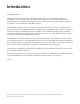
Introduction PatchMate LOOP 8 Guitar players beat our doors down requesting a NEW version of the world famous Rocktron PatchMate....and we have delivered! The PatchMate LOOP 8 provides 128 programmable presets. Eight LOOPs can be configured for multiple purposes. Channel switching, effects LOOPs, guitar routing and more are provided in the PatchMate LOOP 8 The PatchMate LOOP 8 is easy to set up and program with real time user controls. Program the unit from the front panel using the lighted buttons.
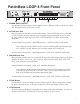
PatchMate LOOP 8 Front Panel 1 POWER Switch and LED Use this switch to turn on and off the PatchMate LOOP 8. When the LED is lit the power will be ON. When the LED is out, the power is OFF.. 2 ACTIVE Input Jack Plug your guitar into this jack to use the buffered input. This ACTIVE Input Jack is connected to an active buffer that helps maintain signal strength when driving multiple devices in parallel. This "buffered" output is present on the "ACTIVE OUTPUT" on the back panel of the PatchMate.
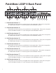
PatchMate LOOP 8 Back Panel � � � � 4 3 2 1 pas.-act. active out out OUT - N.O. OUT - N.O. RETURN RETURN 8 � SEND - N.C. SEND - N.C. IN IN OUT - N.O. OUT - N.O. RETURN RETURN 7 � SEND - N.C. SEND - N.C. IN IN OUT - N.O. OUT - N.O. RETURN RETURN 6 � SEND - N.C. SEND - N.C. IN IN OUT - N.O. OUT - N.O. RETURN RETURN 5 SEND - N.C. SEND - N.C.
PatchMate LOOP 8 Back Panel...continued.... 9 PAS. ACT. OUT Use this jack to plug into the next unit in your signal chain or the desired LOOP. This jack can also be used as an output for the guitar signal when splitting the signal. 10 ACTIVE Jack This jack is used to send your guitar signal to your desired device, such as an amplifier. 11 MIDI OUT/THRU Jack Use this to jack to plug into the first MIDI controllable device in your signal chain. 12 MIDI IN Jack Use this jack to plug in your MIDI controller.
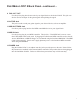
Individual LOOP Jacks Descriptions 1 IN Jack This is the first jack in the signal chain. The audio signal will enter the "LOOP" through this jack. 2 SEND - N.C. Jack This jack is used to send the signal to the desired audio device. 3 RETURN Jack This jack is used to receive the returned signal from the desired audio device.. 4 OUT - N.O. Jack This jack is then used to send the signal to the next LOOP or next device in the signal chain.
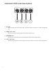
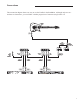
Connections This connection diagram shows one way to use the LOOPs in the PatchMate. Although only two connections are shown here, you can follow a similar progression of connects using LOOPs 3-8.
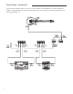
Connections....continued..... This connection diagram shows one way to use the LOOPs in the PatchMate to connect stompboxes (pedals). Although only two connections are shown here, you can follow a similar progression of connects using LOOPs 3-8.
Connections....continued..... This connection diagram shows one way to use the LOOPs in the PatchMate to connect to multiple effects processors.
Connections....continued..... This connection diagram shows one way to use the LOOPs in the PatchMate to connect to two different preamp. 1 OUT - N.O. RETURN SEND - N.C.
Connections....continued..... This connection diagram shows one way to use the LOOPs in the PatchMate to connect two amplifiers and select between the two.
Connections....continued..... This connection diagram shows one way to use the PatchMate's buffered connection.
Connections....continued..... This connection diagram shows one way to use the PatchMates buffered connection to connect to two different preamps.
Connections....continued..... This connection diagram shows one way to connect the PatchMate to "MUTE" an effects processor where parallel effect routings are being implemented.
Connections....continued..... This connection diagram shows how to connect the PatchMate to a MIDI Controller such as the Rocktron MIDI Mate (use similar connections for the Rocktron All Access, All Access LTD and MIDI Xchange. Note: Internal PHANTOM POWER is provided by the PatchMate Loop 8 via the MIDI IN connector pins 6 & 7 and will power your Rocktron MIDI Controller eliminating the need to have a power adatper plugged directly into the MIDI Controller. The power provide is 9VAC.
Setup your PatchMate: To setup your PatchMate please follow these instructions. 1. Press and hold the STORE BUTTON until it begins blinking then release it to enter the MIDI CONFIGURATION PROGRAMMING MODE. 2. The Front panel will be displaying the current MIDI CHANNEL configuration information. To modify the MIDI CHANNEL information press the desired button combination. Once you have made your selections PRESS and RELEASE the STORE BUTTON .
MIDI Channel Select 19
MIDI Controller Setup 3. The FRONT PANEL BUTTONS [ 1 thru 8 ] will blink twice and the STORE BUTTON will start blinking faster signifying that the MIDI CONTROLLER information is now being displayed. 4. You may now make your selections or you may PRESS CANCEL [ 6 ] ON then PRESS and RELEASE the STORE BUTTON . 5. When you are ready to store the information simply PRESS and RELEASE the STORE BUTTON. The STORE BUTTON will blink slowly followed by the recall of preset 1. Programming is now completed.
MIDI Controller Setup *CANCEL: PRESS SWITCH 6 then PRESS and RELEASE the STORE BUTTON to CANCEL the PROGRAMMING MODE. Note: If CANCEL is executed any modified information will not be retained. STEREO LINK: When selected BUTTONS 1-4 will become the control over the linked pairs. [ 1 to 5 ] [ 2 to 6 ] [ 3 to 7 ] [ 4 to 8 ].
Preset Dump MIDI PRESET DUMP PROCEDURE: 1. Press and hold the STORE BUTTON until it begins blinking then release it to enter the MIDI CONFIGURATION PROGRAMMING MODE. 2. PRESS SWITCH [5] TO ILLUMINATE IT [ PRESET DUMP ]. 3) PRESS and RELEASE the STORE BUTTON to execute a dump of all user preset data via MIDI. The STORE BUTTON will blink rapidly during this process.
Setting up the PatchMate using MIDI Program Changes SETTING PatchMate USING MIDI PROGRAM CHANGES Now that you have configured your PatchMate LOOP 8 MIDI CHANNEL to the same channel as your midi controller along with enabling PROGRAM CHANGES ON, you are now ready to program your presets. Make sure you have exited the MIDI CONFIGURATION PROGRAMMING MODE before using your PatchMate LOOP 8 with a Midi Controller. 1. Connect your Midi Controllers MIDI OUT to the PatchMate LOOP 8’s MIDI IN using a 5 PIN MIDI cord.
Setting the PatchMate using MIDI Program Changes..continued.... On the initial reception of this ON state value the target relay will be activated followed by the execution of the delay release timer. Note: When this feature is being used any transmitted value of 0 will be ignored as the delay will handle the off state execution. Therefore Momentary amplifier switching may be attained without the need to provide a momentary controller message.
Rocktron -A Division of GHS Corporation 2813 Wilber Avenue Battle Creek MI 49037 USA Rocktron Phone: 1-(269)-968-3351 Email: info@rocktron.com Check us out on the web at: www.rocktron.com 2008-0001 Rev.